P1000 2nd battery and accessory install ='s hair loss

JoeyL

JoeyL

Well-Known Member
Lifetime Member
Jan 28, 2020
276
741
93
Houston
Ownership

  1. 1000-5
BrotherNov,

dont worry about asking, its not a problem to help you out.

  • i connected the other two terminals on the solenoid on your drawing. this will switch it on when the key is on.
  • pay attention to the instructions that come with your winch, unless it is an Axon it will have another solenoid to wire in and you cannot just connect the + and - terminals to the battery
  • you can hook the winch wires to either the aux battery or the bus bars, whichever is more convenient
1590583647235
 
B

BrotherNov

Well-Known Member
Lifetime Member
Nov 6, 2019
122
281
63
Springfield, IL
Ownership

  1. 1000-5
BrotherNov,

dont worry about asking, its not a problem to help you out.

  • i connected the other two terminals on the solenoid on your drawing. this will switch it on when the key is on.
  • pay attention to the instructions that come with your winch, unless it is an Axon it will have another solenoid to wire in and you cannot just connect the + and - terminals to the battery
  • you can hook the winch wires to either the aux battery or the bus bars, whichever is more convenient
View attachment 204613
Thanks! You're drawing (post 19) is what got me over the hump on this project. Really appreciate your assistance.
 
B

BrotherNov

Well-Known Member
Lifetime Member
Nov 6, 2019
122
281
63
Springfield, IL
Ownership

  1. 1000-5
BrotherNov,

dont worry about asking, its not a problem to help you out.

  • i connected the other two terminals on the solenoid on your drawing. this will switch it on when the key is on.
  • pay attention to the instructions that come with your winch, unless it is an Axon it will have another solenoid to wire in and you cannot just connect the + and - terminals to the battery
  • you can hook the winch wires to either the aux battery or the bus bars, whichever is more convenient
View attachment 204613
I'll obviously use the wires that came with the true isolater for those connections, but what wire size should I buy for everything else? Is 12g large enough?
 
  • Like
Reactions: Papaandhistoys
JoeyL

JoeyL

Well-Known Member
Lifetime Member
Jan 28, 2020
276
741
93
Houston
Ownership

  1. 1000-5
what wire size should I buy for everything else? Is 12g large enough?

I ran all of my main wires as #6AWG because that is what i had on hand (thick lines in my diagram) and based the rest on load and distance. here is a chart that will help steer you in the right direction.
you can use smaller wire on the low amp draw stuff and save some money.
1590591855318


also check my other post
 
B

BrotherNov

Well-Known Member
Lifetime Member
Nov 6, 2019
122
281
63
Springfield, IL
Ownership

  1. 1000-5
So helpful, thanks. Most of my runs will be about 2', so I'm pretty sure 12g or even 14g will be plenty robust.
 
Jgroesbeck

Jgroesbeck

Member
Supporting Member
Apr 21, 2020
34
70
18
U.S.
Ownership

  1. 1000-3
It's all starting to clear up.... Thanks for keeping the thread alive BortherNov. I had to step away from the computer for a week or so. It was nice to come back to see this. Appears I'm only a two bussbars short of being able to start my battery and accessory installs.
 
Jgroesbeck

Jgroesbeck

Member
Supporting Member
Apr 21, 2020
34
70
18
U.S.
Ownership

  1. 1000-3
you got it right. a bus bar is used to make multiple connections to the same source cleanly, without having to stack a bunch of wires on the same terminal. they can be used on the positive or negative side. i used several on mine.


a circuit breaker or fuse is not a bad idea but not required. it protects your wiring from catching on fire if it shorts out. you may end up with nuisance trips if you dont use one thats big enough. check your winch documentation for the max amp draw.

I attached a diagram i made of my setup which is pretty similar to what youre doing. I have posted it before, so maybe you saw it in another thread you were looking at, not sure.

I have a second battery w a True Isolator (complete kit w dual volt meter) and I am also using a stinger 200A relay to switch my power feed to the fuse block. I added a DPDT 3 position (ON/OFF/ON) switch (OTRATTW) to switch between accessory power always on and accessory power on with the key and no accessory power. This switch feeds an "Accessory Bus" that feeds all the small stuff on the dash and also turns on the stinger to provide power to the fuse block.

So far I really like the ability to switch the accessory power. If I am in and out of the buggy a lot i can switch to always on and not interrupt the stereo every time i stop and start. Most other times i just leave it in keyed power mode.

If you dont want the switch the diagram is still basically valid, just eliminate the always on power wire and feed everything with the key on power.


A couple of extra notes:
The Axon winch has an internal relay, so your winch wiring will be a little different.
I should put a fuse in the main that feeds the fuse block, I just haven't done it yet.
I used 6AWG wire for all of the main wiring, it is shown thicker in the diagram.

i attached a pdf of the wiring diagram that is better quality than the attached image if you want to print it out.

View attachment 202452


1. On bus bars, can you connect multiple leads to a single stud? Say a dome light, USB charger, etc...?
2. Which bus bars did you use on your install?
3. Fuse block. Same as above. Can you connect multiple leads to a single stud within the fuse block, assuming multiple connections are low amperage?
4. I purchased a Cole Hersee Solenoid, rated at 65z. After reviewing your plans I will need to send back and get a higher rated solenoid (cold climate): https://m.media-amazon.com/images/I/71hBTYkxNBL._AC_SS350_.jpg
5. You have an inline 3a fuse between your DPDT and + bus bar. Is this because the + coming from the DPDT is not directly wired to the fuse block? Rather it goes through the 200a stinger first?
6. Key on power (from HondaSXS adapter. Is this the wiring harness often referenced? Specifically: KEY ON POWER Harness for Honda Pioneer 1000, 700, 500, and Talon 1000.
7. Dual volt meter relay? What is the function? I don’t recall seeing this in other builds?

I went into shock the first few times I looked at your (and others) wiring diagram. I’m getting a clearer picture now that I’ve been able to review and ask follow-on questions. I can’t thank you enough!
 
Jgroesbeck

Jgroesbeck

Member
Supporting Member
Apr 21, 2020
34
70
18
U.S.
Ownership

  1. 1000-3
This club is fantastic. I'd be no where without it. Well, I'd be a couple thousand $ richer, but still screwed. :)

Yes it is! I extended my vent lines before ever getting it out on the trail. I only did that because of this forum. This weekend, we crossed an unusually high seasonal creek. I had water near the floor boards before getting through it. From better cup holders to vent lines... this forum is solid. As a bonus, I'm learning a metric crap ton about 12v wiring!
 
Last edited:
CID

CID

Well-Known Member
Lifetime Member
Supporting Member
Oct 27, 2019
5,541
25,513
113
SE Denver-ish
Ownership

  1. Talon R
1. On bus bars, can you connect multiple leads to a single stud? Say a dome light, USB charger, etc...?
2. Which bus bars did you use on your install?
3. Fuse block. Same as above. Can you connect multiple leads to a single stud within the fuse block, assuming multiple connections are low amperage?
4. I purchased a Cole Hersee Solenoid, rated at 65z. After reviewing your plans I will need to send back and get a higher rated solenoid (cold climate): https://m.media-amazon.com/images/I/71hBTYkxNBL._AC_SS350_.jpg
5. You have an inline 3a fuse between your DPDT and + bus bar. Is this because the + coming from the DPDT is not directly wired to the fuse block? Rather it goes through the 200a stinger first?
6. Key on power (from HondaSXS adapter. Is this the wiring harness often referenced? Specifically: KEY ON POWER Harness for Honda Pioneer 1000, 700, 500, and Talon 1000.
7. Dual volt meter relay? What is the function? I don’t recall seeing this in other builds?

I went into shock the first few times I looked at your (and others) wiring diagram. I’m getting a clearer picture now that I’ve been able to review and ask follow-on questions. I can’t thank you enough!
1. As long as additional terminals fit, you can stack leads on a single stud. The XTC works this way, there's only two positive (always hot and switched) and one negative stud.

7. The dual volt meter relay is how you turn the VMs off, otherwise they'd stay on. Note that you're usually switching the hot side of the circuit but with the dual VMs, you're switching the ground side.

The round thing in the center is the dual VM. The green and blue leads go directly to the batteries, the dark green is the switched ground (going to the orange relay).
1590598710461
 
advertisement
Jgroesbeck

Jgroesbeck

Member
Supporting Member
Apr 21, 2020
34
70
18
U.S.
Ownership

  1. 1000-3
1. As long as additional terminals fit, you can stack leads on a single stud. The XTC works this way, there's only two positive (always hot and switched) and one negative stud.

7. The dual volt meter relay is how you turn the VMs off, otherwise they'd stay on. Note that you're usually switching the hot side of the circuit but with the dual VMs, you're switching the ground side.

The round thing in the center is the dual VM. The green and blue leads go directly to the batteries, the dark green is the switched ground (going to the orange relay).
View attachment 204663

Ok, I see the VM relay. It's in the True kit I purchased at the SXS store. Makes sense. Thank you very much!
 
  • Like
Reactions: TripleB and CID
CID

CID

Well-Known Member
Lifetime Member
Supporting Member
Oct 27, 2019
5,541
25,513
113
SE Denver-ish
Ownership

  1. Talon R
I also bought the True kit from the SXS store but haven't installed it or the second battery yet. 👍
 
TripleB

TripleB

Well-Known Member
Lifetime Member
Aug 13, 2018
16,236
146,990
113
Caryville, Tennessee
Ownership

  1. 1000-3

  2. 1000-5
4
1. On bus bars, can you connect multiple leads to a single stud? Say a dome light, USB charger, etc...?
2. Which bus bars did you use on your install?
3. Fuse block. Same as above. Can you connect multiple leads to a single stud within the fuse block, assuming multiple connections are low amperage?
4. I purchased a Cole Hersee Solenoid, rated at 65z. After reviewing your plans I will need to send back and get a higher rated solenoid (cold climate): https://m.media-amazon.com/images/I/71hBTYkxNBL._AC_SS350_.jpg
5. You have an inline 3a fuse between your DPDT and + bus bar. Is this because the + coming from the DPDT is not directly wired to the fuse block? Rather it goes through the 200a stinger first?
6. Key on power (from HondaSXS adapter. Is this the wiring harness often referenced? Specifically: KEY ON POWER Harness for Honda Pioneer 1000, 700, 500, and Talon 1000.
7. Dual volt meter relay? What is the function? I don’t recall seeing this in other builds?

I went into shock the first few times I looked at your (and others) wiring diagram. I’m getting a clearer picture now that I’ve been able to review and ask follow-on questions. I can’t thank you enough!
4. I have the same relay on both of my machines and they work perfect. That dude is using a higher amp relay for some reason. I'm sure he has a reason for it but its not needed for what u want to do.
 
  • Like
Reactions: CID
Jgroesbeck

Jgroesbeck

Member
Supporting Member
Apr 21, 2020
34
70
18
U.S.
Ownership

  1. 1000-3
4

4. I have the same relay on both of my machines and they work perfect. That dude is using a higher amp relay for some reason. I'm sure he has a reason for it but its not needed for what u want to do.


Thank you.
 
JoeyL

JoeyL

Well-Known Member
Lifetime Member
Jan 28, 2020
276
741
93
Houston
Ownership

  1. 1000-5
1. On bus bars, can you connect multiple leads to a single stud? Say a dome light, USB charger, etc...?
yes as long as they fit and you dont overload the rating of the entire bar.


2. Which bus bars did you use on your install?

i bought mine at Academy locally, but i think you can find some on Amazon.
Marine Raider 5 + 2 Bus Bar | Academy

DONT BUY THIS ONE (i did at first and returned it) its way too big


3. Fuse block. Same as above. Can you connect multiple leads to a single stud within the fuse block, assuming multiple connections are low amperage?

i bought this one. 6 circuit w cover and negative bus

for sure you can fit two on the same screw, maybe 3. its not the best practice to do it though. your fuse should be protecting your wire and if you have multiple wires you may end up in a situation where it cant do its job

4. I purchased a Cole Hersee Solenoid, rated at 65z. After reviewing your plans I will need to send back and get a higher rated solenoid (cold climate): https://m.media-amazon.com/images/I/71hBTYkxNBL._AC_SS350_.jpg

65z? assuming 65 amps
as long as the sum of your accessories dont exceed the rating it should be fine. i got the stinger because im still not sure what i will add (future proofing a bit) and it was reasonably priced and immediately available.

5. You have an inline 3a fuse between your DPDT and + bus bar. Is this because the + coming from the DPDT is not directly wired to the fuse block? Rather it goes through the 200a stinger first?

so think of this one from the other direction. i have a fuse there because this small wire (14GA i think) is connected directly to the battery via the bus bar. so if you touch it to the frame it will have full amperage from the battery without the fuse - fire hazard.

6. Key on power (from HondaSXS adapter. Is this the wiring harness often referenced? Specifically: KEY ON POWER Harness for Honda Pioneer 1000, 700, 500, and Talon 1000.

yes thats it

7. Dual volt meter relay? What is the function? I don’t recall seeing this in other builds?

it allows you to turn off the display on the volt meter. since the meter is connected to the + side of both batteries, it is always on. So the relay switches the ground connection to break the circuit and turn off the meter. otherwise you would have to switch both + leads on the meter.

here is a pic i had when it was in progress. i dont have a finished pic on me.
bus bars are on the left, stinger is at the top right. you can see the fuse block tro the right of the amplifier, just below and left of the stinger
my wiring is not the prettiest, but it works
IMG 3894
 
Jgroesbeck

Jgroesbeck

Member
Supporting Member
Apr 21, 2020
34
70
18
U.S.
Ownership

  1. 1000-3
yes as long as they fit and you dont overload the rating of the entire bar.


i bought mine at Academy locally, but i think you can find some on Amazon.
Marine Raider 5 + 2 Bus Bar | Academy

DONT BUY THIS ONE (i did at first and returned it) its way too big


i bought this one. 6 circuit w cover and negative bus

for sure you can fit two on the same screw, maybe 3. its not the best practice to do it though. your fuse should be protecting your wire and if you have multiple wires you may end up in a situation where it cant do its job


65z? assuming 65 amps
as long as the sum of your accessories dont exceed the rating it should be fine. i got the stinger because im still not sure what i will add (future proofing a bit) and it was reasonably priced and immediately available.


so think of this one from the other direction. i have a fuse there because this small wire (14GA i think) is connected directly to the battery via the bus bar. so if you touch it to the frame it will have full amperage from the battery without the fuse - fire hazard.


yes thats it


it allows you to turn off the display on the volt meter. since the meter is connected to the + side of both batteries, it is always on. So the relay switches the ground connection to break the circuit and turn off the meter. otherwise you would have to switch both + leads on the meter.

here is a pic i had when it was in progress. i dont have a finished pic on me.
bus bars are on the left, stinger is at the top right. you can see the fuse block tro the right of the amplifier, just below and left of the stinger
my wiring is not the prettiest, but it works
View attachment 204687

Many thanks, I greatly appreciate it. I'm down to understanding the difference between a 7 and 10 pin DPDT switch. Thanks again man.... if we ever catch up, I'll gladly pay in fine food and drink!
 
JoeyL

JoeyL

Well-Known Member
Lifetime Member
Jan 28, 2020
276
741
93
Houston
Ownership

  1. 1000-5
difference between a 7 and 10 pin DPDT switch

the difference is how the lights in the switch are wired. The 10 pin will require you to wire the lights external to the switch and the 7 pin will have the lights internally wired.
I used the 7 pin on mine. But either one will work.
 
Jgroesbeck

Jgroesbeck

Member
Supporting Member
Apr 21, 2020
34
70
18
U.S.
Ownership

  1. 1000-3
the difference is how the lights in the switch are wired. The 10 pin will require you to wire the lights external to the switch and the 7 pin will have the lights internally wired.
I used the 7 pin on mine. But either one will work.

I've got all my components installed minus the switches. My build is like yours with the following exceptions:
-I have a 100a disconnect between the the + bussbar and the Stinger
-I have installed at terrewinch 45
-I do not have (at this time) a radio, usb charger, dash switch lights or amplifier

So at this point, even through I have a fuse box installed, I have nothing going through there except for the stinger, as in your diagram.

I want to wire up my DPDT and winch switch at this time. Other accessories will come later. My switches are OTRATTW:

-DPDT switch: OTRATTW - the Switch Guys Carling Technologies V-Series switches
DPDT rocker: High quality OTRATTW Contura XIV laser-etched rockers
-Winch: High quality OTRATTW Contura XIV laser-etched lower independent LED rocker switches

Questions:
-Will there be issues with the fuse box being wired as in your diagram seeing how I do not have any accessories wired through there right now? I currently have it wired as in your diagram.
-I'm treating my "accessory bus" just like yours. I don't quite understand how your accessory bus is setup and how it works. I understand the "Pos bus" is the pass through for the 12v power coming from the aux battery to the winch, stinger and to the DPDT switch. Is the accessory only used to pass power to the connected accessories you only want on once the DPDT switch allows it, as in always on, key on, and off? Hell, is it that simple?
-Can you help me diagram/understand how to wire up my DPDT and winch? The wiring diagrams for both switches and my winch are in this post.
-On my winch, I do not want to use the "rocker switch" that came with the winch, rather I want to use the OTRATTW winch switch. I would however like to wire up the handheld remote as well.
-Specific to the DPDT:
- Which pin do I wire the key on power harness that I purchased from the SXS store?
- Which pin do I wire the always on power to?
-I assume pin 7 is ran to the neg bus bar?

I can't thank you and others for your patience and help!

Many thanks,
JG

Capture
V1D1JXXB
VJD1D66B
 
JoeyL

JoeyL

Well-Known Member
Lifetime Member
Jan 28, 2020
276
741
93
Houston
Ownership

  1. 1000-5
Questions:
-Will there be issues with the fuse box being wired as in your diagram seeing how I do not have any accessories wired through there right now? I currently have it wired as in your diagram.
No issues. it doesnt care if there is no current running through it.

-I'm treating my "accessory bus" just like yours. I don't quite understand how your accessory bus is setup and how it works. I understand the "Pos bus" is the pass through for the 12v power coming from the aux battery to the winch, stinger and to the DPDT switch. Is the accessory only used to pass power to the connected accessories you only want on once the DPDT switch allows it, as in always on, key on, and off? Hell, is it that simple
yep its that simple. that is exactly correct.
all of the stuff i have connected to my "accessory bus" are just signals with near 0 amperage - such as remote wire for amp, BT receiver, USB charger, etc... Everything you could power off of the accessory plug (cigarette lighter) without overloading that circuit.
and remember, even though its drawn as a bar in the diagram, i used one of these as the "accessory bus"
Amazon.com : wago lever nut
1590606839550.png

its just a convenient place to attach a bunch of wires. the wago lever nut is like a wire nut but for more than just 2-3 wires.

-Can you help me diagram/understand how to wire up my DPDT and winch? The wiring diagrams for both switches and my winch are in this post.
for the DPDT
first - i am pretty sure you have the wrong switch for this - but dont worry, you have the wrong switch for your winch too and it will work out... kind of
this is the switch you need for the accessory power
OTRATTW - the Switch Guys Carling Technologies V-Series switches
the difference is in the detent. the one you have will spring back to the neutral position (everything off) when you let go of it.
however this is exactly what you want to operate the winch.

so for the main DPDT switch:
i stole this from @TripleB's post in the other thread
@TripleB did it better than i did. mine is wired different than this but it still works. i will probably convert mine to this later.
173950 912bfcb0eadebd177022897bbce50e8b jpg
Green is negative. Red to your 2nd battery. Yellow from key on power source. Purple to your relay/stinger.


for your winch, you just follow the diagram you have. just attach the battery to the solenoid instead of directly to the winch like i have in my diagram. then wire the solenoid to the winch as shown.

-On my winch, I do not want to use the "rocker switch" that came with the winch, rather I want to use the OTRATTW winch switch. I would however like to wire up the handheld remote as well.
OK so you will need to use the DPDT switch you already bought to do this. the switch you have for the winch wont work. you can keep it for later and just swap out the rocker when you put in another accessory. that switch can be used to turn something on / off. the winch switch has to be on (in) / off / on (out) and spring back to center.

just remove the factory rocker from the harness if its already wired up to the solenoid.
if i am reading the winch diagram right there is a black, red, and green wire coming out of the back of the switch.
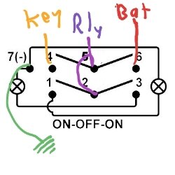
use another wire from your accessory bus and connect to pins 2 and 5.
wire the black and green to 1 and 3
connect 7 to ground (for the lights in the switch)
1592228239880

wire the green and black to the solenoid like the diagram shows.
you will also need to connect from your accessory bus to the red wire on the hand held remote plug for it to work. wire it as shown in the diagram.

if the winch operates backwards you can swap the wires at the back of the switch or on the solenoid


-Specific to the DPDT:
- Which pin do I wire the key on power harness that I purchased from the SXS store?
- Which pin do I wire the always on power to?
-I assume pin 7 is ran to the neg bus bar?
see above
and yes # 7 can go to neg bus bar or any ground connection
 
  • Like
Reactions: BenM and TripleB
Jgroesbeck

Jgroesbeck

Member
Supporting Member
Apr 21, 2020
34
70
18
U.S.
Ownership

  1. 1000-3
No issues. it doesnt care if there is no current running through it.


yep its that simple. that is exactly correct.
all of the stuff i have connected to my "accessory bus" are just signals with near 0 amperage - such as remote wire for amp, BT receiver, USB charger, etc... Everything you could power off of the accessory plug (cigarette lighter) without overloading that circuit.
and remember, even though its drawn as a bar in the diagram, i used one of these as the "accessory bus"
Amazon.com : wago lever nut
1590606839550.png

its just a convenient place to attach a bunch of wires. the wago lever nut is like a wire nut but for more than just 2-3 wires.


for the DPDT
first - i am pretty sure you have the wrong switch for this - but dont worry, you have the wrong switch for your winch too and it will work out... kind of
this is the switch you need for the accessory power
OTRATTW - the Switch Guys Carling Technologies V-Series switches
the difference is in the detent. the one you have will spring back to the neutral position (everything off) when you let go of it.
however this is exactly what you want to operate the winch.

so for the main DPDT switch:
i stole this from @TripleB's post in the other thread
@TripleB did it better than i did. mine is wired different than this but it still works. i will probably convert mine to this later.
View attachment 207894
Green is negative. Red to your 2nd battery. Yellow from key on power source. Purple to your relay/stinger.


for your winch, you just follow the diagram you have. just attach the battery to the solenoid instead of directly to the winch like i have in my diagram. then wire the solenoid to the winch as shown.


OK so you will need to use the DPDT switch you already bought to do this. the switch you have for the winch wont work. you can keep it for later and just swap out the rocker when you put in another accessory. that switch can be used to turn something on / off. the winch switch has to be on (in) / off / on (out) and spring back to center.

just remove the factory rocker from the harness if its already wired up to the solenoid.
if i am reading the winch diagram right there is a black, red, and green wire coming out of the back of the switch.
use another wire from your accessory bus and connect to pins 2 and 5.
wire the black and green to 1 and 3
connect 7 to ground (for the lights in the switch)
View attachment 207892
wire the green and black to the solenoid like the diagram shows.
you will also need to connect from your accessory bus to the red wire on the hand held remote plug for it to work. wire it as shown in the diagram.

if the winch operates backwards you can swap the wires at the back of the switch or on the solenoid


see above
and yes # 7 can go to neg bus bar or any ground connection

I don't believe my DPDT is momentary, there is no spring tension on either of the On positions. When I press the switch in the up or down potion, that's where it stays. I'll assume the switch I have is correct and that the wiring from TripleB's post is correct. Said that, I have no problem with ordering a different switch if it makes the install cleaner, just let me know.

"if i am reading the winch diagram right there is a black, red, and green wire coming out of the back of the switch."

Correct, there is a black, red and green wire from the back of the switch. The black and green are wired with a connector for the back of the winch solenoid. The red is for key on power.

"use another wire from your accessory bus and connect to pins 2 and 5.
wire the black and green to 1 and 3
connect 7 to ground (for the lights in the switch)"

"Green is negative. Red to your 2nd battery. Yellow from key on power source. Purple to your relay/stinger."

Ok, so here goes:
Green is routed to the neg bus bar?
Red (always on power) to the aux battery via the pos bus bar?
Yellow (key on) wired directly to the store key on power harness?
Purple jumped and wired directly to the stinger OR via the accessory bus bar? It looks like it's via the accessory bus bar in your diagram?


I got thinking about the winch being incorrect as I was working on the SXS, thanks for confirming that. I've ordered the following momentary winch switch: High quality OTRATTW Contura V laser-etched LED rocker switches for winches and horns

The new switch wiring diagram is below. Here's my crack at the correct wiring for the new winch rocker:
Pin 7 & 9 - Jump both to the neg bus bar
Pin 8 & 10 - Wire to back of winch solenoid per the instructions in the winch manual. If backwards (in/out) switch the connectors on the winch switch
Pin 2 - wire to the accessory bus

Am I missing anything else?


Winch1
 
advertisement

About us

  • Our community has been around for many years and pride ourselves on offering unbiased, critical discussion among people of all different backgrounds. We are working every day to make sure our community is one of the best.

User Menu

Buy us a beer!

  • Lots of time and money has gone into making sure the community is running the best software, best designs, and all the other bells and whistles. Care to buy us a beer? We'd really appreciate it!

    Beer Fund!

    Club Membership!