P1000 Dual Voltmeter & Dash light help!?

D

Darby

Active Member
Lifetime Member
May 4, 2016
89
199
33
Salem, Oregon
Ownership

  1. 1000-3
While I know that the question I am about to ask had been discussed at length over the years here.... but grant an idiot some leeway please! I have recently purchased a new 2024 Pioneer (3) Dlx.... and going into some extensive (for me) modifications ... A lot of what I am doing is taking what I have done with my 2016 Pioneer - transferring the best of worked for me mods... and upgrading and changing out what wasn't the best.
One of the things that I didn't do on my old SxS... was have a auxiliary fuse Box (I have the Honda aftermarket fuse set up on new bike, with ignition on trigger)... previously on my True Battery isolater setup - i had 2 voltmeters... but they were "on" constantly.... along with my "lighted switches"... now anyone can say, those LED's dont draw much power... but if the SxS sat for extended periods... battery would die. (I keep on a Battery Tender - but still annoying)

ANYWAY.... i'm a week or two into doing the mods... but I have a couple wiring questions that I have tried to research... but all the previous explanations have confused me... i'm probably overthinking how difficult, or easy, what i'm trying to do is... but here are the 2 issues i'm having:

1) I have purchased a dual voltmeter (1 unit - 2 readouts).. that has 3 pins... 1 hot for each battery, and a common ground. I hear the term "negative relay"... I assume that's just the wiring term, not a different kind of Relay? So If I have a normal 4 (or 5 if I need that) pin relay... I assume I'm taking the 2 positive leads from the voltmeter to either side of the true isolater (thereby getting the readings from each battery), How exactly do I wire the Relay what goes on each pin (pin 30 / 87 /86 /85) so that the voltmeters only come on with "key on"??

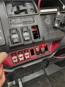
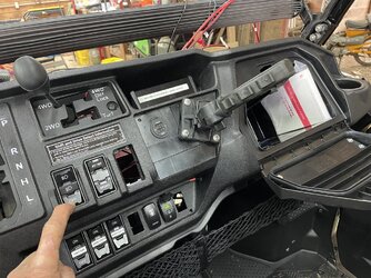
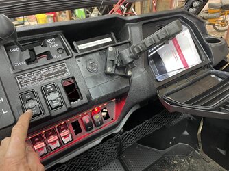
2) Because Honda made the moronic decision to not "light" their switches on this SxS... I have installed a red (easy on the eyes) LED strip that willl light the switches... but I want it to only come on with the factory headlights. Where/how do I tie into that wiring... or fuse... that makes this work the easiest? I previously on my first Pioneer 1000 (8 years ago!) wired the 52" LED to only come on if the main lights were on.... but that was a pain in the butt... tapping into some wire beneath the factory fuses...

I know, I know... pictures.. pictures... pictures... Will do when it's complete.

Anyway... any and all help is greatly appreciated!
 
Last edited:
  • Like
Reactions: TxDoc
DRZRon1

DRZRon1

Well-Known Member
May 11, 2019
1,248
3,981
113
PA
Ownership

  1. Talon X
just wire the ground from the dual voltmeters to a normally open contact on the relay and have the relay wired to come on with the key on power -

thanks for asking -

So it’s basically like putting one test lead of your voltmemeter to the positive of the battery - it reads nothing until you put the other lead on the negative - u are just switching the ground.

technically u can do the positives, just more wiring and using 2 Normally open contacts


all u are doing is connecting/disconnecting the voltmeters - u r correct - they are a parasitic draw along with the clock.

Good luck and yes post some pics
 
Last edited:
bumperm

bumperm

Well-Known Member
May 7, 2021
1,908
6,791
113
Gardnerville, NV
Ownership

  1. 1000-5
What @DRZRon1 said.

Also, while you're having fun with wiring, there's an easy improvement to be had to better assess battery condition with both batteries "at rest". When you turn on the key, the main battery is immediately "loaded", providing power to computers and sub-systems, so the main battery will read lower than it otherwise would. The fix is easy. Install a momentary push button switch to apply ground to the dual-voltmeter's negative terminal in addition to the "relay switched ground wire". Now you can push the button and check both batteries with key off and no load on them.

The wiring for this is simple. A ground can be had at any of the illuminated rocker switches. Connect that ground to one terminal of the momentary push button switch. Then wire the other terminal of this switch to the negative terminal of the dual voltmeter (now there will be two ground wires to the voltmeter terminal).
 
D

Darby

Active Member
Lifetime Member
May 4, 2016
89
199
33
Salem, Oregon
Ownership

  1. 1000-3
just wire the ground from the dual voltmeters to a normally open contact on the relay and have the relay wired to come on with the key on power -

thanks for asking -

So it’s basically like putting one test lead of your voltmemeter to the positive of the battery - it reads nothing until you put the other lead on the negative - u are just switching the ground.

technically u can do the positives, just more wiring and using 2 Normally open contacts


all u are doing is connecting/disconnecting the voltmeters - u r correct - they are a parasitic draw along with the clock.

Good luck and yes post some pics
I truly appreciate the attempt to help me out here... but I'm not really understanding any better than I did previously... i'm aware of what I'm attempting to do... and I know it's possible (i mean, many people have done it already)... Some of what You are telling me assumes I'm smarter than I apparently am! I get the theory... and I know i'm to set it up to finish the circuit with the ground coming on with the key.... what I DON'T know... is what I asked originally asked..." How exactly do I wire the Relay what goes on each pin (pin 30 / 87 /86 /85) so that the voltmeters only come on with "key on"?? What does that look like on the actual relay. IF I'm tying into my switched fuse box.... and lets assume I tie this to "Aux 2" fuse... what am I running to terminal 30 on the relay? What am I running to to 87? to 86?" to 85? which one goes back to the voltmeter?
Sorry for sounding so clueless... but to basically say "wire the relay so it works" ( i'm aware!) isn't getting me closer to my solution :)
 
D

Darby

Active Member
Lifetime Member
May 4, 2016
89
199
33
Salem, Oregon
Ownership

  1. 1000-3
What @DRZRon1 said.

Also, while you're having fun with wiring, there's an easy improvement to be had to better assess battery condition with both batteries "at rest". When you turn on the key, the main battery is immediately "loaded", providing power to computers and sub-systems, so the main battery will read lower than it otherwise would. The fix is easy. Install a momentary push button switch to apply ground to the dual-voltmeter's negative terminal in addition to the "relay switched ground wire". Now you can push the button and check both batteries with key off and no load on them.

The wiring for this is simple. A ground can be had at any of the illuminated rocker switches. Connect that ground to one terminal of the momentary push button switch. Then wire the other terminal of this switch to the negative terminal of the dual voltmeter (now there will be two ground wires to the voltmeter terminal).
Thanks for the suggestion.... that does sound pretty easy to do... but i'm good with seeing the voltage with the key on... i'm not looking for more buttons on the rig! Right now I have : Light Bar, Rock Lights, Rear Lights, Interior Lights, Stereo, winch power, Winch in/out, USB, dual volt meter, horn... and upright gun rack.... Also doing the switch lights and glovebox lights (want tied to headlight switch)..... outside the cockpit - rear bumper, Tough Country front bumper with stinger for spraying with 100 gallon tank and 16' boom, Viper 5000# winch w/wireless remote, and Elka stage 5 shocks.... Also set up for a bolt on "hunting box" in the bed when hunting...... Love the rig... just need help with the 2 items listed in the post... :)
 
Rayger143

Rayger143

Well-Known Member
Lifetime Member
Supporting Member
Aug 5, 2020
3,133
27,497
113
Winfield, BC Canada
Ownership

  1. 1000-5
Thanks for the suggestion.... that does sound pretty easy to do... but i'm good with seeing the voltage with the key on... i'm not looking for more buttons on the rig! Right now I have : Light Bar, Rock Lights, Rear Lights, Interior Lights, Stereo, winch power, Winch in/out, USB, dual volt meter, horn... and upright gun rack.... Also doing the switch lights and glovebox lights (want tied to headlight switch)..... outside the cockpit - rear bumper, Tough Country front bumper with stinger for spraying with 100 gallon tank and 16' boom, Viper 5000# winch w/wireless remote, and Elka stage 5 shocks.... Also set up for a bolt on "hunting box" in the bed when hunting...... Love the rig... just need help with the 2 items listed in the post... :)
IMG 8869
IMG 8869
 
D

Darby

Active Member
Lifetime Member
May 4, 2016
89
199
33
Salem, Oregon
Ownership

  1. 1000-3
You ROCK Dude! Exactly what I need! Thanks! I've gotten headaches trying to find this answer!
 
  • Like
Reactions: Rayger143
Mark in Northern Iowa

Mark in Northern Iowa

Well-Known Member
Club Contributor
Oct 20, 2021
490
2,193
93
Floyd County, Iowa
kramnella.wixsite.com
Ownership

  1. 1000-3
Hey now, that there powerpoint design looks just like mine. haha!!
Glad it is being used and helping new owners. 👍
.
The original switched hot negative.
Switched hot negative

and the original thread
.
Here is what the front side looks like.
power off
Volt key off

push button
Volt key off push

.
Have a good day
 
Last edited:
  • Like
  • Love
Reactions: CID and Darby
D

Darby

Active Member
Lifetime Member
May 4, 2016
89
199
33
Salem, Oregon
Ownership

  1. 1000-3
Now if only someone has a quick and easy answer for tying the dash./glovebox lights to the factory headlights...????
 
Mark in Northern Iowa

Mark in Northern Iowa

Well-Known Member
Club Contributor
Oct 20, 2021
490
2,193
93
Floyd County, Iowa
kramnella.wixsite.com
Ownership

  1. 1000-3
Now if only someone has a quick and easy answer for tying the dash./glovebox lights to the factory headlights...????
I'm going to look and see if I can find it, but I do not remember which fuse in the box I used for my dash lights.
Can you use the high beam trigger from the store?
.
.
Have a good day
 
Last edited:
advertisement
D

Darby

Active Member
Lifetime Member
May 4, 2016
89
199
33
Salem, Oregon
Ownership

  1. 1000-3
I do realize that is an "option"... but was really wanting it to come on whenever the lights are turned on..... not necessarily when "hi beams" are activated.... My 1st Pioneer... i set up by tapping into the light fuse .... but was hoping for an "easier" solution... because I remember that sucked.
 
Mark in Northern Iowa

Mark in Northern Iowa

Well-Known Member
Club Contributor
Oct 20, 2021
490
2,193
93
Floyd County, Iowa
kramnella.wixsite.com
Ownership

  1. 1000-3
Knew it was here somewhere. haha
Post #2 is for the "light on power" wire to tap into.
.
Even though, I am pretty sure I used a fuse tap for my dash switch lights.
No, I do not remember which fuse it was. haha I'll try and look tomorrow.
Was told that it was not the recommended way, but my rig is mainly on the farm.
.
Have a good day
 
Last edited:
  • Like
Reactions: CID
D

Darby

Active Member
Lifetime Member
May 4, 2016
89
199
33
Salem, Oregon
Ownership

  1. 1000-3
Mark... thanks... I had read that post waaaay back when I did that on my 2016 Pioneer (I had tied my 52" LED bar to only be able to come on if lights were on). My problem is... the wiring harness for the 2024 model, and light switch (toggle vs twist knob), are different than the 2016 model that the post was referring to. Probably tell by the dirt, which one is new! hahaha
So still need help! :)

IMG 6743 IMG 6744
 
bumperm

bumperm

Well-Known Member
May 7, 2021
1,908
6,791
113
Gardnerville, NV
Ownership

  1. 1000-5
If I'm understanding the question correctly, you can use a rectifier diode like this: DIODE to simply and economically accomplish the automatic light switching.

A diode acts like a one-way check valve for current flow, allowing current flow in only one direction. The diode is a handy and cheap (less than a buck) way to control current flow in many applications*. Example: If you connect the banded end (cathode) of the diode to the positive terminal of light "B", and then connect to other end of "anode" of the diode to the positive terminal of light "A", the lights will operate thusly:

When light A is switched on, light B will also turn on - both lights on.

When light B is switched on, light A will not turn on (unless its switch or circuit is separately turned on).

*I'm using a diode to provide switched power to my radio but I don't want that power to be applied to any other circuits that are on Aux power. When the ignition is on, power is applied to the radio IF the radio switch is on. This power comes through an added isolation diode. Then there is a separate switch that applies power to the radio from the aux battery - it works anytime, ignition on or off. The diode prevents Aux power from back feeding power to main power circuits. This could all be accomplished with a relay circuit, but a diode is simpler, cheaper, and more reliable long-term.
 
Last edited:
  • Like
Reactions: Darby
D

Darby

Active Member
Lifetime Member
May 4, 2016
89
199
33
Salem, Oregon
Ownership

  1. 1000-3
that sounds awesome... I will look into this. it's not like a lot of current we are talking here... any idea where I tie into the "light power"? At the headlamp itself?
 
bumperm

bumperm

Well-Known Member
May 7, 2021
1,908
6,791
113
Gardnerville, NV
Ownership

  1. 1000-5
that sounds awesome... I will look into this. it's not like a lot of current we are talking here... any idea where I tie into the "light power"? At the headlamp itself?
Tie it in where it's most convenient, length of run will be minimal and where the wiring will be neat. That might be at a fuse panel, light switch, or at the light itself.
 
  • Like
Reactions: Mlm
D

Darby

Active Member
Lifetime Member
May 4, 2016
89
199
33
Salem, Oregon
Ownership

  1. 1000-3
Thanks for all the help! Got both problems dealt with... Thanks to Rayger143 and Mark in Northern Iowa for passing on the diagram of wiring the Relay for the dual voltmeter... and to HondaSxS thru private messaging explained to me how to tie into the tail light wire for "lights on power" for my dash and glovebox! You guys ROCK!

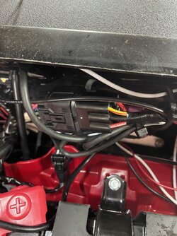
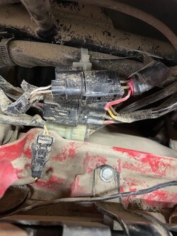
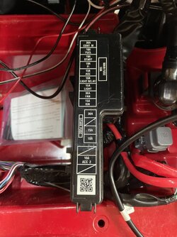
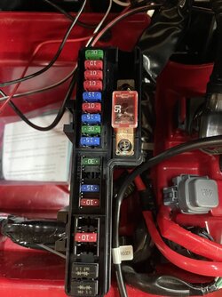
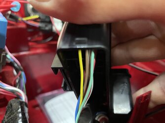
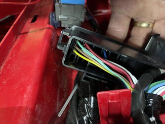
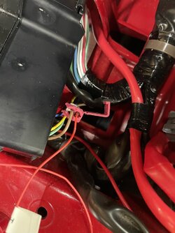
Below are some pictures of the dash and glovebox lights and wiring..... basically tapped into the brown center wire under the fuse box... it's easier because it's the end fuse (closest to You as you stand facing the bike)...

IMG 6746 IMG 6748 IMG 6749 IMG 6750 IMG 6751 IMG 6754 IMG 6755 IMG 6756
 
Last edited by a moderator:
D

Darby

Active Member
Lifetime Member
May 4, 2016
89
199
33
Salem, Oregon
Ownership

  1. 1000-3
What @DRZRon1 said.

Also, while you're having fun with wiring, there's an easy improvement to be had to better assess battery condition with both batteries "at rest". When you turn on the key, the main battery is immediately "loaded", providing power to computers and sub-systems, so the main battery will read lower than it otherwise would. The fix is easy. Install a momentary push button switch to apply ground to the dual-voltmeter's negative terminal in addition to the "relay switched ground wire". Now you can push the button and check both batteries with key off and no load on them.

The wiring for this is simple. A ground can be had at any of the illuminated rocker switches. Connect that ground to one terminal of the momentary push button switch. Then wire the other terminal of this switch to the negative terminal of the dual voltmeter (now there will be two ground wires to the voltmeter terminal).
Quit giving me ideas! Had a momentary switch laying around, and thought..."gee... why not do that, just for s***s and giggles?".. so I did. :)
 
D

Darby

Active Member
Lifetime Member
May 4, 2016
89
199
33
Salem, Oregon
Ownership

  1. 1000-3
If I'm understanding the question correctly, you can use a rectifier diode like this: DIODE to simply and economically accomplish the automatic light switching.

A diode acts like a one-way check valve for current flow, allowing current flow in only one direction. The diode is a handy and cheap (less than a buck) way to control current flow in many applications*. Example: If you connect the banded end (cathode) of the diode to the positive terminal of light "B", and then connect to other end of "anode" of the diode to the positive terminal of light "A", the lights will operate thusly:

When light A is switched on, light B will also turn on - both lights on.

When light B is switched on, light A will not turn on (unless its switch or circuit is separately turned on).

*I'm using a diode to provide switched power to my radio but I don't want that power to be applied to any other circuits that are on Aux power. When the ignition is on, power is applied to the radio IF the radio switch is on. This power comes through an added isolation diode. Then there is a separate switch that applies power to the radio from the aux battery - it works anytime, ignition on or off. The diode prevents Aux power from back feeding power to main power circuits. This could all be accomplished with a relay circuit, but a diode is simpler, cheaper, and more reliable long-term.
I liked what you explained here on how you deal with your radio,... and I want to do that. I have my Noam 4 channel stereo hooked up through a relay (don't know that is totally necessary, as I ran a Noam 4 channel on my older Pioneer without the benefit of a relay, and the switch never had a problem with it - anyway, I digress... i do have a Relay this time).. was planning on powering it up through the Honda "key on fuse box". But at times I want to just listen to the stereo without having the key on. So trying to figure out ... am I just doubling up the power wires (one direct from Aux Battery, and one from the Relay, via the fusebox) on the switch, and then put the Diode where? Between the Key On Fusebox and the Relay? In this instance - the LED in the Stereo switch will always be on. Perhaps I put a second switch on the dashboard for "key off stereo"... and run the Aux battery to it, and then to the main stereo switch... denying it 'power" when key is off, unless secondary switch is "on".? thoughts?
 
advertisement

About us

  • Our community has been around for many years and pride ourselves on offering unbiased, critical discussion among people of all different backgrounds. We are working every day to make sure our community is one of the best.

User Menu

Buy us a beer!

  • Lots of time and money has gone into making sure the community is running the best software, best designs, and all the other bells and whistles. Care to buy us a beer? We'd really appreciate it!

    Beer Fund!

    Club Membership!