Universal SATV EPS install sand rail

O

ob1jeeper

Well-Known Member
Dec 20, 2019
97
281
53
Arizona
Ownership

  1. 1000-5
After having good luck with the SATV EPS Kit install in my P-1000-5, I purchased another SATV EPS kit for my sand rail.

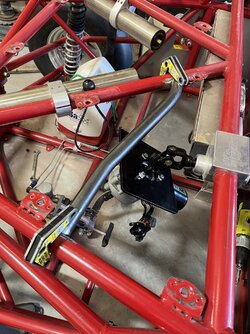
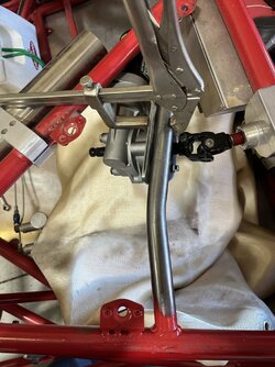
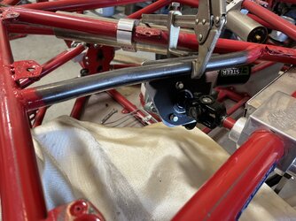
Got started yesterday with the install, requiring a bit of fabrication in order to mount the gear. A few pics of progress, while I await the paint drying before proceeding to the wiring and bolt-up of the gear.

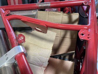
First up was fab of a "c/mbr" on which to mount the gear mounting plate.

IMG 4291


IMG 4292


Trimmed excess material from the gear mount plate, verified location/position, then welded to new "C/Mbr"
IMG 4296


IMG 4302
IMG 4303


IMG 4289 IMG 4298 IMG 4299 IMG 4304 IMG 4305
 
O

ob1jeeper

Well-Known Member
Dec 20, 2019
97
281
53
Arizona
Ownership

  1. 1000-5
Well as happens, life got in the way, but today, I got back to it, and finished the install but still need to re-install the frt. pass. seat
(removed for wiring loom routing), re-install the Rt side body skin, and clean up the work-space, but it's done enough for a friday evening... ;)

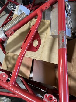
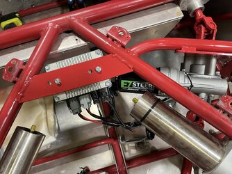
In my haste the other day, I forgot to account for the ECM mounting, so had to fab a mount for it as well.
IMG 4317


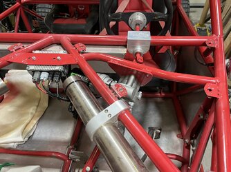
Since I wanted to retain the upper end of the steering column, for my quick-release steering wheel, I chucked one of the supplied shafts and joints in the lathe, and cut the welds loose from the U-joint, then turned the forward end of the original upper shaft in the lathe to make it mate up with the supplied u-joint.
IMG 4327


IMG 4328


The kit provides two shaft-U-joint pieces from which to fabricate useable steering. Here, I used the lower end of the shaft/u-joint assy to the rack&pinion gear. Since both the rack & the supplied gear are mounted such that the intermediate shaft needs to come apart in order to both install, or remove either of the gears. I elected to splice the shaft, using a piece of tubing that wasn't as snug a fit as I felt necessary, so to ensure it was a solid and tight fitment, I cut the splice tube lengthways, shortened the shafts as required to mate up, then clamped it all together, and drilled the splice and both shafts to accept 5/16 grade 5 machine screws.
IMG 4329


Finally after paint had dried, I was able to complete final mounting and wiring.
IMG 4330


And all that work is now hidden... ;)
IMG 4335

IMG 4336


PS: I absolutely LOVE the low steering efforts now... ;) IMG 4331 IMG 4332