S
Hello, first thread. I thought I would detail out my installation. I will have to say thanks to all who have posted on their builds which assisted me greatly in my build.
1. Cooper Bussman Fuse Box (Purchased on EBay)
2. Genuine Marine Systems 6 Switch Panel, Volt Meter, USB Charger, Cig Lighter (Purchased on Amazon)
3. Secondary Battery (Purchased from Throttle X Batteries)
4. Grounding Strip (Purchased on Amazon)
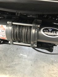
5. 4,500lbs Moto Alliance Winch
6. 32" Curved Mictuning LED Light Bar
7. 13" Mictuning LED Light Bar (Rear ROPs Bar)
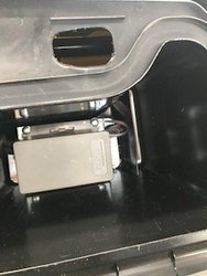
First thing I did was mounted the Fuse Box in the glove box. To accomplish this I had to trim a piece off of the mounting bracket. I then cut a piece of plywood the same pattern as the inside base of the glove box. I then painted it black so it is almost undetectable in the glove box. I drilled two holes and used 2 - 1/4 20 bolts, 2 Fender washers and 2 lock nuts to attach to the glove box. Once fitted I marked (removed fuse box) and drilled two holes for the wires. One hole was for the switch wires and fused wires. The second hole was for the Power and Ground wires. I had to use a right angle drill for both holes. I used 2 grommets to protect the wires coming through the glove box.
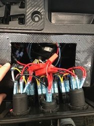
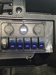
Next step I removed the warning placard from the dash and outlined the switch plate. I ended up making a template to ensure everything was centered. I gut the hole utilizing an air body saw. I replaced one of the rocker switches with a plow rocker switch. I then used the 2nd Rocker switch for the front light, 3rd Switch for the rear light. The 4th switch was used to power the 12 V Cig Lighter and the USB charger. I pulled Key on power by utilizing a fuse tap from the 15A accessory fuse. Since the fuse tap sits above the other fused I slotted the fuse box cover so it would slip back down onto the fuse box. It kind of clipped back into place but I ended up using 2 zip ties to secure the fuse box cover.
The fuse tap is powering 3 items the volt meter, winch contactor and Fuse panel key on power. I only used a 10 amp fuse in case there is an over draw situation. I made leads with terminal ends that I soldered to the fuse tap for each of the accessories being powered.
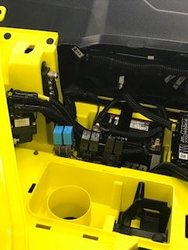
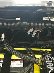
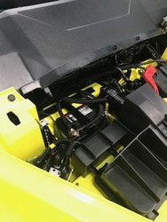
All of the grounds were run to a central grounding strip that is connected to the secondary battery. The Bussman Fuse box is directly connected to the secondary battery.
All of the power wires and grounding wires were labeled utilizing a label maker.
My goal was to be as independent of the factory wiring harness as possible. Besides the holes in the glove box and dash everything can be put back to factory. Should there be an issue with the secondary wiring I can remove the power cable and shut it down.
Hopefully this thread helps someone else!


