So I'm finally documenting my build. Over the past year I've added quite a few mods and so here it goes...
You are using an out of date browser. It may not display this or other websites correctly.
You should upgrade or use an alternative browser.
You should upgrade or use an alternative browser.
My first main project was an auxiliary battery to support all the new electrical additions I wanted. I wanted to keep it separate from the stock system so as to never drain my start battery, and never have any interference at all. All I wanted the stock system to do was be able to charge this aux battery after the stock battery was good to go.
Here is what I ended up with. And yes I may have gone a little overkill on some of these items, meaning a larger than necessary model or whatnot, but it all works great! Sorry some of the pics aren't the greatest, I'll try to take better ones later.
- Optima Yellow Top: 8014-045 D34/78 placed under drivers seat
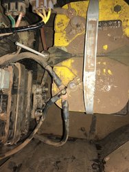
- Connected to a 200A circuit breaker
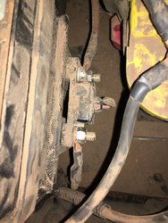
- Continued on to True UTV-SBI-15 Smart Isolator, to allow stock system to charge aux system and separating the two.
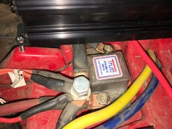
- Power from Aux battery isn't 'available' or 'on' until triggered through a Master Aux Switch which triggers a Stinger SGP32 200A Isolator/Relay
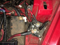
- After triggered on through relay, power connects to Bussmann Fuse Box as well as Blue Sea Systems ST Blade 12-circuit Fuse Block. (This Blue Sea Fuse block is definitely one of the overkill things I did. I needed a few more fuse outlets than the 10 I had available from the Bussman and so I should have gone with just a 6-circuit without negative, but once I realized this, it was past the amazon return window so I just kept the 12 circuit.)
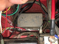
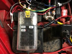
- Speaking of Negatives, all my grounds are wired to a Blue Sea Systems 20-screw 150A bus bar.
- My heavy duty battery wiring is 4 gauge premium welding cable, with 5/16 and 3/8 lug ring terminals.
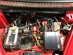
- This is what it currently looks like (April 2018). Looks like a mess but that's just because many of the wires are so long and I have a bunch of extra just going everywhere. I do have quite a few things wired up so that naturally adds to the birds nest of wires, and things like my Amp add a TON of extra wires which is crazy. It's actually a pretty clean install overall and some of those long extras should get removed when I add some things down the road.
Standby for the next part...
Here is what I ended up with. And yes I may have gone a little overkill on some of these items, meaning a larger than necessary model or whatnot, but it all works great! Sorry some of the pics aren't the greatest, I'll try to take better ones later.
- Optima Yellow Top: 8014-045 D34/78 placed under drivers seat

- Connected to a 200A circuit breaker

- Continued on to True UTV-SBI-15 Smart Isolator, to allow stock system to charge aux system and separating the two.

- Power from Aux battery isn't 'available' or 'on' until triggered through a Master Aux Switch which triggers a Stinger SGP32 200A Isolator/Relay

- After triggered on through relay, power connects to Bussmann Fuse Box as well as Blue Sea Systems ST Blade 12-circuit Fuse Block. (This Blue Sea Fuse block is definitely one of the overkill things I did. I needed a few more fuse outlets than the 10 I had available from the Bussman and so I should have gone with just a 6-circuit without negative, but once I realized this, it was past the amazon return window so I just kept the 12 circuit.)


- Speaking of Negatives, all my grounds are wired to a Blue Sea Systems 20-screw 150A bus bar.
- My heavy duty battery wiring is 4 gauge premium welding cable, with 5/16 and 3/8 lug ring terminals.
- This is what it currently looks like (April 2018). Looks like a mess but that's just because many of the wires are so long and I have a bunch of extra just going everywhere. I do have quite a few things wired up so that naturally adds to the birds nest of wires, and things like my Amp add a TON of extra wires which is crazy. It's actually a pretty clean install overall and some of those long extras should get removed when I add some things down the road.

Standby for the next part...
Next up....controlling everything, with switches!
I spent a lot of time thinking (and dreaming) of everything I wanted to add to my Pioneer. I spent months drooling over everyone else's rig on here and seeing what you all did. I took what I liked and came up with my own plan. And here is how that turned out....
Sorry about some of the pics. I didn't always remember to take them before I got started on putting things together.
Once I decided how many switches and which stereo I wanted, I determined I couldn't really get it all on to one panel, so I decided to go with two which meant coming up with a solution for the lower in-dash cubby hole.
For the main plate I went with @mystic1219 switch panel, which is of course awesome!
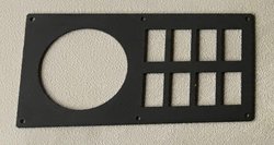
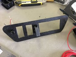
For the lower cubby hole I built my own. I used some 1/8" ABS. Getting it cut to the appropriate size with the correct radius' was no easy task, (at least for me it wasn't). But I finally figured it out and then got it cut, which a jig saw took care of fairly easily, although very messily...It fit perfectly! I was stoked. Unfortunately my cutting of the switch holes didn't go quite as well, so some of them have a little slop in them but nothing too horrible. Someday I hope to try and come up with a better plate.
The majority of my switches and rockers came from OTRATTW and are Lower Independent, and are Green/Amber LED. This means the lower LED with words is lit (Amber) when the switch has power going to it (usually from dash lights, but not in my case. I'll explain how I did mine later). And the upper LED with the symbol is lit (Green) when turned on. Most of these are SPST switches. One different switch I got from OTRATTW is my winch switch which is a momentary DPDT.
However I also needed a DPST switch for my voltmeters which I ended up getting from Spemco. I also got all my switch mounting panels from them as well.
And the last switch I got was my winch power switch and is a guarded aircraft-type SPST.
I have two other things that work in conjunction with my switches, and that is a dimmer for my cab lights and a variable speed controller for my under seat fan.
Lastly, although not a switch per-se, it sits with them and is the same size, my mictuning voltmeter.
Next up....wiring!
I spent a lot of time thinking (and dreaming) of everything I wanted to add to my Pioneer. I spent months drooling over everyone else's rig on here and seeing what you all did. I took what I liked and came up with my own plan. And here is how that turned out....
Sorry about some of the pics. I didn't always remember to take them before I got started on putting things together.
Once I decided how many switches and which stereo I wanted, I determined I couldn't really get it all on to one panel, so I decided to go with two which meant coming up with a solution for the lower in-dash cubby hole.
For the main plate I went with @mystic1219 switch panel, which is of course awesome!

For the lower cubby hole I built my own. I used some 1/8" ABS. Getting it cut to the appropriate size with the correct radius' was no easy task, (at least for me it wasn't). But I finally figured it out and then got it cut, which a jig saw took care of fairly easily, although very messily...It fit perfectly! I was stoked. Unfortunately my cutting of the switch holes didn't go quite as well, so some of them have a little slop in them but nothing too horrible. Someday I hope to try and come up with a better plate.

The majority of my switches and rockers came from OTRATTW and are Lower Independent, and are Green/Amber LED. This means the lower LED with words is lit (Amber) when the switch has power going to it (usually from dash lights, but not in my case. I'll explain how I did mine later). And the upper LED with the symbol is lit (Green) when turned on. Most of these are SPST switches. One different switch I got from OTRATTW is my winch switch which is a momentary DPDT.
However I also needed a DPST switch for my voltmeters which I ended up getting from Spemco. I also got all my switch mounting panels from them as well.
And the last switch I got was my winch power switch and is a guarded aircraft-type SPST.
I have two other things that work in conjunction with my switches, and that is a dimmer for my cab lights and a variable speed controller for my under seat fan.
Lastly, although not a switch per-se, it sits with them and is the same size, my mictuning voltmeter.
Next up....wiring!
Alright, I’m finally getting to this. Sorry for the delay folks.
The Wiring:
Wiring has definitely been the most time consuming of this entire project so far. I had spent moths coming up with a wiring blueprint, which was quite helpful during the actual task. Most of the time however, I would just have to stop and really think about the device, the switch, the flow of current and what I wanted it to do. This helped me piece things together slowly but surely.
I have found that color-coding is a LIFESAVER when working large wiring projects. Every wire coming from the Bussman is a different color and so I made sure to stick with that theme. I ended up ordering a few packages of colored wire bundles from www.wirebarn.com. Great source of automotive wiring and very quick shipping!
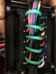
I bought an 11-pack of 12-gauge TXL as well as a 16-gauge pack. Each color contained 25’ of wire. Knowing I would use a bunch of Red for miscellaneous HOT wires and Black for NEG/GRND wires I bought a couple extra rolls of each color both in 16 and 18 gauge.
For all my connections I used heat-shrink butt and spade connectors. These kits from Amazon were really good quality. Also for a lot of these connections I also used dual wall adhesive heat shrink tubing to completely cover the connection. This particular kit of tubing is the best I’ve found and used thus far. (Note: I did run out of some of the sizes because I used so much, so order extras if you have a big project like this). What I like about the heat shrink tubing is, not only does this make the connection sealed and now waterproof, it also strengthens the connection. If you’re like me you’ve had the occasional wire pull right out of the butt or spade connection after crimping. A good crimp of course should not allow this to happen, but hey, sometimes it does. This additional tubing just gives an extra strength to the connection regardless.
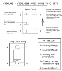
Another heat shrink tubing I used were these little numbered pieces. To help me keep track of which wire went into which side of my connector plugs (details on those below) I used these to mark them. Since I had two wires coming from most of my switches, and my switches once installed were buried too deep to trace wires back to to see, I marked them with a 2 and 3 respectively so I knew which pin on the switch they came from 2 or 3. If you have no idea what I’m talking about look at the back of your switch or diagram and you’ll see a bunch of pins. This is probably the most standard one shown here. Not only did I label the 2/3 wires individually, I also labeled the two as a bundle to the correlating Fuse they went to in the Bussman, reference pic above. (Example shown below: wires coming from my Backup Lights Switch go to Fuse 8 in the Bussman so they bundled together and I labeled them 8. This just helps me personally in addition to the colors as well as for knowing fuse slots.)
In addition to wiring colors and heat shrink numbers, I used a label maker to label almost everything. Mostly for the fact that months and years down the road I will have NO clue what goes to where. And with soooo many wires in such a small area tracing them is an extremely difficult task. Labeling makes life so much easier!
With all this heat shrinking, a good heat gun was very helpful. This one from Amazon is really awesome. But it gets HOT! I accidently got a fairly good-sized 2nd degree burn when my wrist barely touched the end of the nozzle. OUCH!
A good pair of crimpers and wire strippers is an absolute necessity! This pair of Irwins is awesome and cut a lot of time out of the process. I love this tool!
I also used a lot of cable sleeve. I especially used this any time wires left the ‘under the hood’ areas such as through the engine bay, wheel wells, along the frame and also while routing up the ROPS bars to get to upper in-cab components. It keeps things a lot cleaner and more organized. It does however take a bit of time to run all the cables through it and you really have to think about it all well in advance of starting to run any wires.
Those wires that went through the engine bay and wheel wells that were even more exposed to the elements got even additional protection with split wire loom conduit.
Finally, I wanted all of my connections, or at least as many as possible to be quickly disconnected so I could either change or move them, or if I wanted the wiring to go to a different accessory or something down the road. There’s nothing worse than needing to disconnect a wire that you just crimped and heat shrunk the connector and also the extra heat shrink tubing around. And I have a history of sometimes making the connection and doing all that before thinking of the process a couple steps farther along that requires that one actually not be connected yet. So I learned from my past mistakes and decided to make connections and disconnects much simpler.
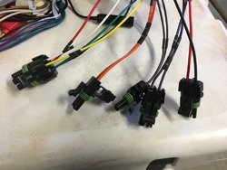
Therefore, I decided on using Delphi Weatherpack Connectors. These things are awesome! They aren’t cheap but they make life so much easier and I believe are totally worth it. I ordered a large Weatherpack Kit from www.allelectronics.com as well as some additional connector kits, just because the large kit didn’t contain enough 1 and 2 pin connectors for what I’d need. You’ll need a special crimping tool for these and of course Amazon comes through again with this one.
This type of connection/kit really steps up your game. I believe it creates a better look as well as makes it all more functional. However, it is a little more time consuming and you really need to pay attention to the pins and seals you’re using and the connections you’re making. Once I got the hang of it I actually really enjoyed making these connections. It was actually a lot of fun and I felt like a pro!
There were several times I needed a good soldered connection rather than crimped. I’ve always cheaped out on soldering tools in the past with things like battery powered or the small butane powered solderers. And they have always sucked and broken so finally I bought something legit. This guy, and I’m happy I did. So easy to use and has made all my soldering painless from that of the past!
Alright, I think that about does it for all the specialty tools and products I used for wiring this project up, so lets check out some pictures.
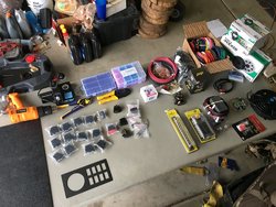
Here is everything before the mayhem begins!
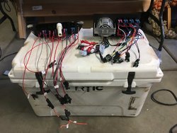
Here are both of my switch panels completed! So many wires!! This includes almost everything (switch wise) on my Pioneer. I do have a few others that aren't in these panels and are cut directly into the dash, so this isn't all inclusive LOL.
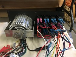
My main panel with stereo. I think I did a decent job bridging things and overall it turned out fairly clean. I'm sure there's a few things I could have done to make it a bit cleaner but oh well, It all works really well and that's all that matters.
My lower cubby panel
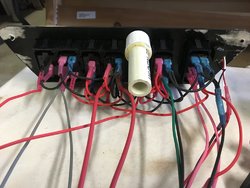
And finally just some of the connections
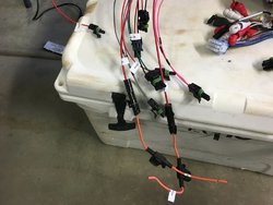

After all of this was done I had to put the mating connectors on the wires coming from the Bussman or the Blue Sea Systems Fuse Block to the appropriate switch and do the same to the accessory and then everything just simply push connected real easily!
Next, I'll show you how it all came together! The end result of all this wiring!
The Wiring:
Wiring has definitely been the most time consuming of this entire project so far. I had spent moths coming up with a wiring blueprint, which was quite helpful during the actual task. Most of the time however, I would just have to stop and really think about the device, the switch, the flow of current and what I wanted it to do. This helped me piece things together slowly but surely.
I have found that color-coding is a LIFESAVER when working large wiring projects. Every wire coming from the Bussman is a different color and so I made sure to stick with that theme. I ended up ordering a few packages of colored wire bundles from www.wirebarn.com. Great source of automotive wiring and very quick shipping!

I bought an 11-pack of 12-gauge TXL as well as a 16-gauge pack. Each color contained 25’ of wire. Knowing I would use a bunch of Red for miscellaneous HOT wires and Black for NEG/GRND wires I bought a couple extra rolls of each color both in 16 and 18 gauge.
For all my connections I used heat-shrink butt and spade connectors. These kits from Amazon were really good quality. Also for a lot of these connections I also used dual wall adhesive heat shrink tubing to completely cover the connection. This particular kit of tubing is the best I’ve found and used thus far. (Note: I did run out of some of the sizes because I used so much, so order extras if you have a big project like this). What I like about the heat shrink tubing is, not only does this make the connection sealed and now waterproof, it also strengthens the connection. If you’re like me you’ve had the occasional wire pull right out of the butt or spade connection after crimping. A good crimp of course should not allow this to happen, but hey, sometimes it does. This additional tubing just gives an extra strength to the connection regardless.
Another heat shrink tubing I used were these little numbered pieces. To help me keep track of which wire went into which side of my connector plugs (details on those below) I used these to mark them. Since I had two wires coming from most of my switches, and my switches once installed were buried too deep to trace wires back to to see, I marked them with a 2 and 3 respectively so I knew which pin on the switch they came from 2 or 3. If you have no idea what I’m talking about look at the back of your switch or diagram and you’ll see a bunch of pins. This is probably the most standard one shown here. Not only did I label the 2/3 wires individually, I also labeled the two as a bundle to the correlating Fuse they went to in the Bussman, reference pic above. (Example shown below: wires coming from my Backup Lights Switch go to Fuse 8 in the Bussman so they bundled together and I labeled them 8. This just helps me personally in addition to the colors as well as for knowing fuse slots.)
In addition to wiring colors and heat shrink numbers, I used a label maker to label almost everything. Mostly for the fact that months and years down the road I will have NO clue what goes to where. And with soooo many wires in such a small area tracing them is an extremely difficult task. Labeling makes life so much easier!


With all this heat shrinking, a good heat gun was very helpful. This one from Amazon is really awesome. But it gets HOT! I accidently got a fairly good-sized 2nd degree burn when my wrist barely touched the end of the nozzle. OUCH!
A good pair of crimpers and wire strippers is an absolute necessity! This pair of Irwins is awesome and cut a lot of time out of the process. I love this tool!
I also used a lot of cable sleeve. I especially used this any time wires left the ‘under the hood’ areas such as through the engine bay, wheel wells, along the frame and also while routing up the ROPS bars to get to upper in-cab components. It keeps things a lot cleaner and more organized. It does however take a bit of time to run all the cables through it and you really have to think about it all well in advance of starting to run any wires.
Those wires that went through the engine bay and wheel wells that were even more exposed to the elements got even additional protection with split wire loom conduit.
Finally, I wanted all of my connections, or at least as many as possible to be quickly disconnected so I could either change or move them, or if I wanted the wiring to go to a different accessory or something down the road. There’s nothing worse than needing to disconnect a wire that you just crimped and heat shrunk the connector and also the extra heat shrink tubing around. And I have a history of sometimes making the connection and doing all that before thinking of the process a couple steps farther along that requires that one actually not be connected yet. So I learned from my past mistakes and decided to make connections and disconnects much simpler.
Therefore, I decided on using Delphi Weatherpack Connectors. These things are awesome! They aren’t cheap but they make life so much easier and I believe are totally worth it. I ordered a large Weatherpack Kit from www.allelectronics.com as well as some additional connector kits, just because the large kit didn’t contain enough 1 and 2 pin connectors for what I’d need. You’ll need a special crimping tool for these and of course Amazon comes through again with this one.
This type of connection/kit really steps up your game. I believe it creates a better look as well as makes it all more functional. However, it is a little more time consuming and you really need to pay attention to the pins and seals you’re using and the connections you’re making. Once I got the hang of it I actually really enjoyed making these connections. It was actually a lot of fun and I felt like a pro!
There were several times I needed a good soldered connection rather than crimped. I’ve always cheaped out on soldering tools in the past with things like battery powered or the small butane powered solderers. And they have always sucked and broken so finally I bought something legit. This guy, and I’m happy I did. So easy to use and has made all my soldering painless from that of the past!
Alright, I think that about does it for all the specialty tools and products I used for wiring this project up, so lets check out some pictures.
Here is everything before the mayhem begins!

Here are both of my switch panels completed! So many wires!! This includes almost everything (switch wise) on my Pioneer. I do have a few others that aren't in these panels and are cut directly into the dash, so this isn't all inclusive LOL.

My main panel with stereo. I think I did a decent job bridging things and overall it turned out fairly clean. I'm sure there's a few things I could have done to make it a bit cleaner but oh well, It all works really well and that's all that matters.

My lower cubby panel

And finally just some of the connections


After all of this was done I had to put the mating connectors on the wires coming from the Bussman or the Blue Sea Systems Fuse Block to the appropriate switch and do the same to the accessory and then everything just simply push connected real easily!
Next, I'll show you how it all came together! The end result of all this wiring!
Last edited:
Hondasxs
Club Founder
Staff member
Lifetime Member
Supporting Member
That's a lot of wires!!!!!
Yes it is! Prob a few more switches and therefore wires than is really necessary, but for me and what I wanted in the end, it worked out.
Brave man.
I looked at building this with my 700. Then i relized there was no way I could figure all that out.
Found one on amazon and just boight it. Lol.
Sent from my HTC6545LVW using Tapatalk
I kind of thought the same thing until I put pencil to paper to draw it all out and it started making sense and then during the project I definitely had to really think about what was going on to make it happen. But it is completely doable for anyone, it just takes some time and thinking to accomplish.
So what was the result of all that painstaking work of what seems like a mess of wiring? Here, it is.
I placed my switches in a fashion that made the most sense to me, Ergonomically and Logically. Mostly so that I could reach for them and for the most part know what I was hitting without needing to fully think about it or even read the switch, at least for some important ones. For example, the backup light switch is right under the shifter, so when I shift into reverse, I can look back, my hand falls off the shifter and straight down to the first switch and voila, I have lights for where I'm already looking. When I'm ready to put it back into forward gear my hand can do the same thing without a glance at my panel. I did the same with my LED light bar. When I'm cruising down the road at 55MPH at night and around the corner comes head on traffic. I want to blind them with my light bar for as little time as possible, yet at that speed I don't want to be "heads down" looking at my switch panel searching for which switch it is I need to turn off, I know it's one of the closest to where my hands currently are on the steering wheel and it's the bottom one of the first row and can find it quickly by feel.
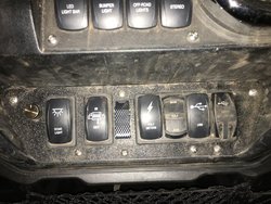
My two switch panels which contain the majority of my swithces
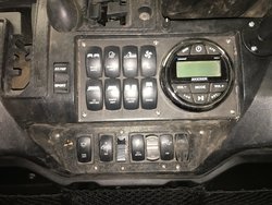
And here they are powered up with the Master Aux switch on.
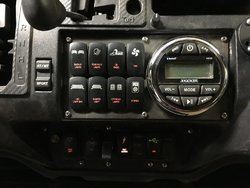
Upper panel. You can see a small dial just above the panel between the Fan switch and the Stereo. This is the variable speed controller for the under the seat fan.
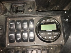
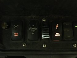
Lower cubby pocket panel. You can see the small dial to the left of the Dome Light switch. This is the brightness intensity controller for my interior dome lights.
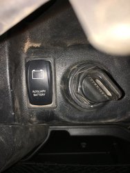
Master Aux Switch – Nothing on my switch panel is functional unless this switch is on, except for the voltmeters/switch since those are hardwired directly to each battery.
As you can see the winch switch isn’t lit up, that’s because in this state it has no power. I wired it this way to prevent accidental bumps (mainly from my 3 little nephews and future kids), which potentially could put a lot of strain on the winch that is already reeled in tight or just doesn’t need to be moved unintentionally/dangerously at all during a winching scenario.
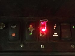
Once this aircraft style guarded switch is flipped, then my winch switch has power to operate.
Sorry I don't have one of my voltmeters turned on. I'll have to add that pic later.
Overall it turned out really great! I'm extremely happy with it! Like I mentioned in one of my earlier posts, the lower cubby pocket panel ended up with a little play in some of the switch cutouts but not enough to be a real issue. Other than that I'm really not sure I would have changed much anything by doing it over again.
Next I'll start showing some of my accessories and add-ons.
I placed my switches in a fashion that made the most sense to me, Ergonomically and Logically. Mostly so that I could reach for them and for the most part know what I was hitting without needing to fully think about it or even read the switch, at least for some important ones. For example, the backup light switch is right under the shifter, so when I shift into reverse, I can look back, my hand falls off the shifter and straight down to the first switch and voila, I have lights for where I'm already looking. When I'm ready to put it back into forward gear my hand can do the same thing without a glance at my panel. I did the same with my LED light bar. When I'm cruising down the road at 55MPH at night and around the corner comes head on traffic. I want to blind them with my light bar for as little time as possible, yet at that speed I don't want to be "heads down" looking at my switch panel searching for which switch it is I need to turn off, I know it's one of the closest to where my hands currently are on the steering wheel and it's the bottom one of the first row and can find it quickly by feel.
My two switch panels which contain the majority of my swithces

And here they are powered up with the Master Aux switch on.

Upper panel. You can see a small dial just above the panel between the Fan switch and the Stereo. This is the variable speed controller for the under the seat fan.

Lower cubby pocket panel. You can see the small dial to the left of the Dome Light switch. This is the brightness intensity controller for my interior dome lights.

Master Aux Switch – Nothing on my switch panel is functional unless this switch is on, except for the voltmeters/switch since those are hardwired directly to each battery.

As you can see the winch switch isn’t lit up, that’s because in this state it has no power. I wired it this way to prevent accidental bumps (mainly from my 3 little nephews and future kids), which potentially could put a lot of strain on the winch that is already reeled in tight or just doesn’t need to be moved unintentionally/dangerously at all during a winching scenario.

Once this aircraft style guarded switch is flipped, then my winch switch has power to operate.

Sorry I don't have one of my voltmeters turned on. I'll have to add that pic later.
Overall it turned out really great! I'm extremely happy with it! Like I mentioned in one of my earlier posts, the lower cubby pocket panel ended up with a little play in some of the switch cutouts but not enough to be a real issue. Other than that I'm really not sure I would have changed much anything by doing it over again.
Next I'll start showing some of my accessories and add-ons.
Last edited:
Eltobgi
Well-Known Member
Lifetime Member
Supporting Member
Club Contributor
So...what’s the total $ invested
I will have to get back to you on that one. Honestly haven't gotten around to making my spreadsheet on it yet. I'm afraid it's going to be more than I care to admit LOL. I know it wasn't cheap.
Eltobgi
Well-Known Member
Lifetime Member
Supporting Member
Club Contributor
Lol, you don’t have to tell me! I have to estimate on cost per pound of weight addedI will have to get back to you on that one. Honestly haven't gotten around to making my spreadsheet on it yet. I'm afraid it's going to be more than I care to admit LOL. I know it wasn't cheap.
Lol, you don’t have to tell me! I have to estimate on cost per pound of weight added
Just spent a couple hrs looking up my receipts/orders and inputting it into my excel, been meaning to do that for a while now.
And now I'm a little shell shocked! Up to this documented point in the project I'm in it for about $1300 in parts/materials and another $140 in tools.
Now realize these few things about my project. I go overboard. First, I am a buy it nice or buy it twice kinda guy and so I also usually go for top of the line parts/materials/etc. not always necessary but that's just how I buy. Second, I bought some of these things bigger than necessary. For example the relay and the circuit breaker I went with a 200A, easily could have saved a few bucks on each for a slightly smaller size, or gone with a smaller battery not a full size Optima. Third, some of these expenses were kits where I only used a few parts of the kit (connectors, wire, etc.) Those weatherpack connectors are NOT cheap. Some I used a lot from the kit, and some I have a TON leftover for my next 10 years of projects LOL. And lastly, I ordered a few extras of things which I ended up not using nor returning, such as switches/rocker bodies, and those things start adding up.
In reality I could have cut out prob $200 easily and kept my project almost identical to what it is. Anyone else doing the same setup but without some of the gucci stuff could prob save at least $500 if not more. I just have a lot of extras which most people won't.
Looks great! I bet you spent more time planning this out than executing it! I've been adding switches as I add accessories but your way is much more efficient in the long run. Great idea with the guarded switch. I too have a separate power switch for my winch for the same reasons. Just look at one photo of a Pioneer's front bumper caved in from the winch being accidentally activated and you'll see why.
E
elkguide
Well-Known Member
Lifetime Member
Supporting Member
So...what’s the total $ invested
If you have to ask...….. YOU CAN'T AFFORD IT!!!!!!!!!!!
Eltobgi
Well-Known Member
Lifetime Member
Supporting Member
Club Contributor
Have you seen my buildIf you have to ask...….. YOU CAN'T AFFORD IT!!!!!!!!!!!
Looks great! I bet you spent more time planning this out than executing it! I've been adding switches as I add accessories but your way is much more efficient in the long run. Great idea with the guarded switch. I too have a separate power switch for my winch for the same reasons. Just look at one photo of a Pioneer's front bumper caved in from the winch being accidentally activated and you'll see why.
Thank you! Yes I spent a very long time planning it out, I have a full powerpoint for a wiring diagram LOL. That's exactly why I went a little overboard. I tried thinking of everything I might want either now or down the road and wired a switch up for it. Much easier in my opinion that removing things and adding new parts in down the road. As of now I have 3 switches that aren't hooked up to any accessory yet. The good thing is, if I decide I want a different accessory I just need to pop off the switch faceplate and put on whatever I want.
Looking really good!
Thank you very much!
Windrock1000
Move out of the way! I'm lost?
Lifetime Member
Looks great young Jedi!Alright, I’m finally getting to this. Sorry for the delay folks.
The Wiring:
Wiring has definitely been the most time consuming of this entire project so far. I had spent moths coming up with a wiring blueprint, which was quite helpful during the actual task. Most of the time however, I would just have to stop and really think about the device, the switch, the flow of current and what I wanted it to do. This helped me piece things together slowly but surely.
I have found that color-coding is a LIFESAVER when working large wiring projects. Every wire coming from the Bussman is a different color and so I made sure to stick with that theme. I ended up ordering a few packages of colored wire bundles from www.wirebarn.com. Great source of automotive wiring and very quick shipping!
View attachment 77753
I bought an 11-pack of 12-gauge TXL as well as a 16-gauge pack. Each color contained 25’ of wire. Knowing I would use a bunch of Red for miscellaneous HOT wires and Black for NEG/GRND wires I bought a couple extra rolls of each color both in 16 and 18 gauge.
For all my connections I used heat-shrink butt and spade connectors. These kits from Amazon were really good quality. Also for a lot of these connections I also used dual wall adhesive heat shrink tubing to completely cover the connection. This particular kit of tubing is the best I’ve found and used thus far. (Note: I did run out of some of the sizes because I used so much, so order extras if you have a big project like this). What I like about the heat shrink tubing is, not only does this make the connection sealed and now waterproof, it also strengthens the connection. If you’re like me you’ve had the occasional wire pull right out of the butt or spade connection after crimping. A good crimp of course should not allow this to happen, but hey, sometimes it does. This additional tubing just gives an extra strength to the connection regardless.
Another heat shrink tubing I used were these little numbered pieces. To help me keep track of which wire went into which side of my connector plugs (details on those below) I used these to mark them. Since I had two wires coming from most of my switches, and my switches once installed were buried too deep to trace wires back to to see, I marked them with a 2 and 3 respectively so I knew which pin on the switch they came from 2 or 3. If you have no idea what I’m talking about look at the back of your switch or diagram and you’ll see a bunch of pins. This is probably the most standard one shown here. Not only did I label the 2/3 wires individually, I also labeled the two as a bundle to the correlating Fuse they went to in the Bussman, reference pic above. (Example shown below: wires coming from my Backup Lights Switch go to Fuse 8 in the Bussman so they bundled together and I labeled them 8. This just helps me personally in addition to the colors as well as for knowing fuse slots.)
In addition to wiring colors and heat shrink numbers, I used a label maker to label almost everything. Mostly for the fact that months and years down the road I will have NO clue what goes to where. And with soooo many wires in such a small area tracing them is an extremely difficult task. Labeling makes life so much easier!
View attachment 77754
View attachment 77756
With all this heat shrinking, a good heat gun was very helpful. This one from Amazon is really awesome. But it gets HOT! I accidently got a fairly good-sized 2nd degree burn when my wrist barely touched the end of the nozzle. OUCH!
A good pair of crimpers and wire strippers is an absolute necessity! This pair of Irwins is awesome and cut a lot of time out of the process. I love this tool!
I also used a lot of cable sleeve. I especially used this any time wires left the ‘under the hood’ areas such as through the engine bay, wheel wells, along the frame and also while routing up the ROPS bars to get to upper in-cab components. It keeps things a lot cleaner and more organized. It does however take a bit of time to run all the cables through it and you really have to think about it all well in advance of starting to run any wires.
Those wires that went through the engine bay and wheel wells that were even more exposed to the elements got even additional protection with split wire loom conduit.
Finally, I wanted all of my connections, or at least as many as possible to be quickly disconnected so I could either change or move them, or if I wanted the wiring to go to a different accessory or something down the road. There’s nothing worse than needing to disconnect a wire that you just crimped and heat shrunk the connector and also the extra heat shrink tubing around. And I have a history of sometimes making the connection and doing all that before thinking of the process a couple steps farther along that requires that one actually not be connected yet. So I learned from my past mistakes and decided to make connections and disconnects much simpler.
Therefore, I decided on using Delphi Weatherpack Connectors. These things are awesome! They aren’t cheap but they make life so much easier and I believe are totally worth it. I ordered a large Weatherpack Kit from www.allelectronics.com as well as some additional connector kits, just because the large kit didn’t contain enough 1 and 2 pin connectors for what I’d need. You’ll need a special crimping tool for these and of course Amazon comes through again with this one.
This type of connection/kit really steps up your game. I believe it creates a better look as well as makes it all more functional. However, it is a little more time consuming and you really need to pay attention to the pins and seals you’re using and the connections you’re making. Once I got the hang of it I actually really enjoyed making these connections. It was actually a lot of fun and I felt like a pro!
There were several times I needed a good soldered connection rather than crimped. I’ve always cheaped out on soldering tools in the past with things like battery powered or the small butane powered solderers. And they have always sucked and broken so finally I bought something legit. This guy, and I’m happy I did. So easy to use and has made all my soldering painless from that of the past!
Alright, I think that about does it for all the specialty tools and products I used for wiring this project up, so lets check out some pictures.
Here is everything before the mayhem begins!
View attachment 77757
Here are both of my switch panels completed! So many wires!! This includes almost everything (switch wise) on my Pioneer. I do have a few others that aren't in these panels and are cut directly into the dash, so this isn't all inclusive LOL.
View attachment 77758
My main panel with stereo. I think I did a decent job bridging things and overall it turned out fairly clean. I'm sure there's a few things I could have done to make it a bit cleaner but oh well, It all works really well and that's all that matters.
View attachment 77760
My lower cubby panel
View attachment 77759
And finally just some of the connections
View attachment 77761
View attachment 77756
After all of this was done I had to put the mating connectors on the wires coming from the Bussman or the Blue Sea Systems Fuse Block to the appropriate switch and do the same to the accessory and then everything just simply push connected real easily!
Next, I'll show you how it all came together! The end result of all this wiring!
Looks great young Jedi!
Thanks! I most definitely couldn't have done it without this forum. Everyones ideas and knowledge on here is simply amazing!

