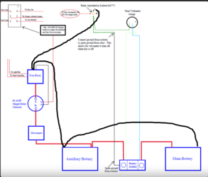
P1000m5 Dual Battery Diagram...Sorry in advance.

Spadoo

Spadoo

Member
Lifetime Member
Supporting Member
May 30, 2024
13
47
13
Northern California
Ownership

  1. 1000-5
Hello! First I want to apologize to everyone in advance as I know this topic has been posted many times before. My issue is that I am in no way an electrician nor someone who even understands electrical design. Yet, I am going to attempt to install a dual battery system this weekend on my new 2024 1000-5 Forest I recently purchased.

I have watched almost every Youtube video available and read through TONS of threads and discussions on the forum regarding this. There was SO MUCH information and more than one way to do this, so I decided to use bits and pieces from many of your system and create one that suites my needs. I just ask that anyone with experience take a quick look and let me know if what I came up will work. I am open to criticism and any and all suggestions. Thank you in advance!

One of the main goals I wanted to integrate into this system is the ON/OFF/ON rocker switch to have the ability to run the dual system with Key-On Power / OFF / Auxiliary Battery Only (when machine is off).

What I have purchased:
Additionally, I have an assortment of wire/cable, connectors, terminals, in-line fuses, add-a-circuit fuse taps, diodes, jumpers and rocker switches. Basically if there is something needing to be added to the below diagram, I probably have it and can add it to the system if needed.

I have omitted most the grounding system to make the diagram less jumbled.

1717445483752
 

Attachments

  • Secondary Battery Wiring Diagram.pdf
    45.2 KB · Views: 52
As an Amazon Associate we earn from qualifying purchases.
  • Like
Reactions: Rayger143 and TxDoc
RacinJasonWV

RacinJasonWV

Active Member
Aug 8, 2022
52
156
33
WV
Ownership

  1. 1000-5
I’m not much help but wanted to share how I got around the lack of ground wire on the newer models.

I did some swapping around with the factory battery wires to make things work.

Basically swapped the winch ground from the main battery over to the secondary and used the kit ground to go from winch control to main battery. They tie together at the winch controller.

Winch factory hot moved from starter solenoid over to the isolator where it ties into the second battery (2nd battery and winch both on isolator post). Then tied the isolator to the factory hot on the starter solenoid with the short kit wire.

IMG 0071
IMG 0072
IMG 0385
IMG 0386
 
Last edited:
Spadoo

Spadoo

Member
Lifetime Member
Supporting Member
May 30, 2024
13
47
13
Northern California
Ownership

  1. 1000-5
I’m not much help but wanted to share how I got around the lack of ground wire on the newer models.

I did some swapping around with the factory battery wires to make things work.

Basically swapped the winch ground from the main battery over to the secondary and used the kit ground to go from winch control to main battery. They tie together at the winch controller.

Winch factory hot moved from starter solenoid over to the isolator where it ties into the second battery (2nd battery and winch both on isolator post). Then tied the isolator to the factory hot on the starter solenoid with the short kit wire.

View attachment 431457View attachment 431458View attachment 431459View attachment 431460
Thank you! I appreciate any and all suggestions from those who have done this modification already. Also, your post reminded me that I need to move my factory winch onto the aux battery as well.
 
  • Like
Reactions: Rayger143
Hondasxs

Hondasxs

Club Founder
Staff member
Lifetime Member
Supporting Member
Feb 13, 2013
18,186
64,901
113
Charlotte, NC
HondaSxS.com
Ownership

  1. 1000-5

  2. Talon R
I'm glad to see someone understand the alternative wiring of the isolator using the spare ground off the relay. I think this may be a better option than what most of us do.

Fuse box choice - Consider one that has a ground buss on it. Your diagram shows you grounding to the fuse box but the one you selected is not capable of that as it is positive only.

Want to simplify the switch wiring for the stinger? I have an item for you --> Pre-Wired Relay Control Switch for AUX and Key-on usage. For Stinger, Cole Hersee or any.
Nothing wrong with yours. its just basic DPDT switch.

I'm adding back the grounds. :D

dont see much else really.....
You mentioned buss bars, I feel like they just add confusion. If you choose to add one as you said it must be placed correctly. I see many wire diagrams that are incorrect when using a positive and negative buss bar.

1717551485255
 
Last edited:
Hondasxs

Hondasxs

Club Founder
Staff member
Lifetime Member
Supporting Member
Feb 13, 2013
18,186
64,901
113
Charlotte, NC
HondaSxS.com
Ownership

  1. 1000-5

  2. Talon R
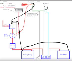
You only need 1 key-on tap for your rocker switch.
Everything after the stinger is now switched. Might as well have the volt meter on it as well.
Or, you can also put it on the fuse block, sharing a power port with something small like USB ports or dome light.

1717551682655
 
Spadoo

Spadoo

Member
Lifetime Member
Supporting Member
May 30, 2024
13
47
13
Northern California
Ownership

  1. 1000-5
I'm glad to see someone understand the alternative wiring of the isolator using the spare ground off the relay. I think this may be a better option than what most of us do.

Fuse box choice - Consider one that has a ground buss on it. Your diagram shows you grounding to the fuse box but the one you selected is not capable of that as it is positive only.

Want to simplify the switch wiring for the stinger? I have an item for you --> Pre-Wired Relay Control Switch for AUX and Key-on usage. For Stinger, Cole Hersee or any.
Nothing wrong with yours. its just basic DPDT switch.

I'm adding back the grounds. :D

dont see much else really.....
You mentioned buss bars, I feel like they just add confusion. If you choose to add one as you said it must be placed correctly. I see many wire diagrams that are incorrect when using a positive and negative buss bar.

View attachment 431567
Thank you for taking a look and confirming, as well as adding your comments! Puts my mind at ease. I spent a lot of time combing through forum posts and watching videos to try and understand how to best put together this system.

You are correct on the fuse box. I will be (unfortunately) adding a negative bus and only because I wont have the time to get a different fuse box prior to the install.

As for the club store switch...I stumbled across it a couple days ago, a bit too late for my install. My Pioneer is stored at our cabin, so I unfortunately I do not have enough time to get that switch before I head up there on Thursday to perform the install. I still may order your switch and integrate it at a later date since it is definitely more plug and play than what I will be doing.
 
  • Like
Reactions: ChadD
Spadoo

Spadoo

Member
Lifetime Member
Supporting Member
May 30, 2024
13
47
13
Northern California
Ownership

  1. 1000-5
You only need 1 key-on tap for your rocker switch.
Everything after the stinger is now switched. Might as well have the volt meter on it as well.
Or, you can also put it on the fuse block, sharing a power port with something small like USB ports or dome light.

View attachment 431568
So, for the one key-on tap, connect to DPDT switch to key-on as shown and run the volt meter relay power straight to the fuse block? Do this because the key-on tap will already be connected to the system via the DPDT switch from the stinger solenoid?

Sorry if I am not understanding correctly. I have a lot to learn about this wiring stuff.
 
  • Like
Reactions: ChadD
Hondasxs

Hondasxs

Club Founder
Staff member
Lifetime Member
Supporting Member
Feb 13, 2013
18,186
64,901
113
Charlotte, NC
HondaSxS.com
Ownership

  1. 1000-5

  2. Talon R
So, for the one key-on tap, connect to DPDT switch to key-on as shown and run the volt meter relay power straight to the fuse block? Do this because the key-on tap will already be connected to the system via the DPDT switch from the stinger solenoid?

Sorry if I am not understanding correctly. I have a lot to learn about this wiring stuff.
Yes.
No issue doing it either way.

You have to make a decision:
When using key-off power. Do you want the volt meter to read?


Sent from my SM-G996U using Tapatalk
 
  • Like
Reactions: ChadD and Spadoo
Spadoo

Spadoo

Member
Lifetime Member
Supporting Member
May 30, 2024
13
47
13
Northern California
Ownership

  1. 1000-5
Yes.
No issue doing it either way.

You have to make a decision:
When using key-off power. Do you want the volt meter to read?


Sent from my SM-G996U using Tapatalk
Understood, thank you. I would think it to be beneficial to be able to view the volt meter in the key-off position so when running accessories on aux battery, I would be aware of battery drain.
 
bumperm

bumperm

Well-Known Member
May 7, 2021
1,859
6,674
113
Gardnerville, NV
Ownership

  1. 1000-5
A simple solution, to be able to view both battery voltages at any time, is to install a normally open momentary push button on the dash. One side goes to ground, the other side goes to the ground terminal on the voltmeter. The advantage of this arrangement is that it allows you to check the main battery when it's not being either charged or discharged, i.e. with no-load and it displays both battery voltages "no-load" for comparison.
 
  • Like
Reactions: ChadD and Spadoo
advertisement