N
You are using an out of date browser. It may not display this or other websites correctly.
You should upgrade or use an alternative browser.
You should upgrade or use an alternative browser.
educ8tedguess
Well-Known Member
Lifetime Member
How much of the plastics is everyone taking off to do the wiring. Just a quick look tells me that a lot needs to come off the front . Also, where are you running your "frame ground?" Is there a spot already or do I need to create my own
nbomar
Well-Known Member
Lifetime Member
I removed no plastic. I did hook the lower lights to a keyed hot. The upper lights are hooked up so they light up no matter what when the switch it activated.
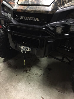
I didn't remove any plastic at all. I ran my chassis ground to a bolt on the front of the frame above the winch mounting location. I just checked for a good bolt. I wouldn't worry too much about that as long as you find a good spot.
I didn't remove any plastic at all. I ran my chassis ground to a bolt on the front of the frame above the winch mounting location. I just checked for a good bolt. I wouldn't worry too much about that as long as you find a good spot.
I intend to remove as little plastics as possible.
I think/hope that with the distribution module,
it can all be done under the hood, other than
running the wires to the switches on the dash.
John
I think/hope that with the distribution module,
it can all be done under the hood, other than
running the wires to the switches on the dash.
John
educ8tedguess
Well-Known Member
Lifetime Member
Good to hear. I was worried that I would have to get to the auxiliary outlet all the way in the back or right to the ignition for the keyed hot. I will do a little more playing around before I look at removing plastics. ThanksI removed no plastic. I did hook the lower lights to a keyed hot. The upper lights are hooked up so they light up no matter what when the switch it activated.
I didn't remove any plastic at all. I ran my chassis ground to a bolt on the front of the frame above the winch mounting location. I just checked for a good bolt. I wouldn't worry too much about that as long as you find a good spot.
nbomar
Well-Known Member
Lifetime Member
What about spod?
I used on on my jeep and they have A general one that can be easily installed in UTV. I think I am going this route.
I used on on my jeep and they have A general one that can be easily installed in UTV. I think I am going this route.
educ8tedguess
Well-Known Member
Lifetime Member
Switch plate is wired, isolator is in, distribution box is in and winch is mounted. Now I need to wire the lights (when I get them). And I didn't remove any plastics... Thanks to everyone that has contributed or is contributing to this thread. I wouldn't have been able to do it if it wasn't for this.
N
As I start mounting my switches, I expect that I will not place or wire all at once, but rather add as needed. I know how the individual switches are wired, but is there a switch plate that will take a universal ground and power connect so that all the switches can be powered and grounded with short pre-built jumper wires? I expect ground can be jumped from switch to switch, although input power to each switch is low and output power is managed through the relay's, it's probably not correct to jumper power from switch to switch???? What is the neat way to get power to each switch without an individual hot to each one? If this is a really dumb question, please forgive me, be patient, and help grow and nurture my inner electrician. 
Hondasxs
Club Founder
Staff member
Lifetime Member
Supporting Member
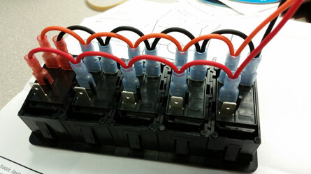
Here are 2 example wire diagrams to use with the switches.
Keep in mind that switches can have different pin layouts, see the correct layout for your switch.
Draw it out on paper before hand. Check and recheck or you will short the switch like I have done.
1 - This can be used without relays up to max switch capabilities.
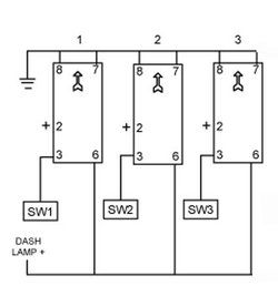
2 - This is jumping both ground, illumination, and low amp power for a relay setup. **Notice the pin layout is different from above but same concept can apply to any switch.
In this setup: Red - power in, - Orange - power from headlights, Black - Ground, Blank is power out to relay.
PS. This is pushing the extent of my electrical knowledge as I consider myself a novice also. But the 1000 will make my 3rd setup like this I have done successfully.
To those in the know. Feel free to jump in.
Keep in mind that switches can have different pin layouts, see the correct layout for your switch.
Draw it out on paper before hand. Check and recheck or you will short the switch like I have done.
1 - This can be used without relays up to max switch capabilities.

2 - This is jumping both ground, illumination, and low amp power for a relay setup. **Notice the pin layout is different from above but same concept can apply to any switch.
In this setup: Red - power in, - Orange - power from headlights, Black - Ground, Blank is power out to relay.

PS. This is pushing the extent of my electrical knowledge as I consider myself a novice also. But the 1000 will make my 3rd setup like this I have done successfully.
To those in the know. Feel free to jump in.
advertisement
educ8tedguess
Well-Known Member
Lifetime Member
Your setup 2 is how I did mine. I am a total novice when it comes to electrical stuff. My dad came over and helped me understand what I was doing. After watching someone who knows their way around this stuff, I almost think you need to be able to think a certain way to get it right. I clearly don't have the electrician gene...Here are 2 example wire diagrams to use with the switches.
Keep in mind that switches can have different pin layouts, see the correct layout for your switch.
Draw it out on paper before hand. Check and recheck or you will short the switch like I have done.
1 - This can be used without relays up to max switch capabilities.
View attachment 8172
2 - This is jumping both ground, illumination, and low amp power for a relay setup. **Notice the pin layout is different from above but same concept can apply to any switch.
In this setup: Red - power in, - Orange - power from headlights, Black - Ground, Blank is power out to relay.
View attachment 8173
PS. This is pushing the extent of my electrical knowledge as I consider myself a novice also. But the 1000 will make my 3rd setup like this I have done successfully.
To those in the know. Feel free to jump in.
SXS,
This looks great and will greatly simplify
the wiring requirements that go to the
switch panel. I know someone showed
something similar earlier in this thread,
but this helps me tremendously. I have
a good concept of things electrical,
but this makes it easy.
What switch assy is that? From
OTRTTW?
I am just waiting on my battery
solenoid, to install my second
battery, and wire in my winch.
I was thinking of just running my
winch through the corded remote,
and only running lights on my switch
panel. Does that seem reasonable?
Thanks again!
John
Here are 2 example wire diagrams to use with the switches.
Keep in mind that switches can have different pin layouts, see the correct layout for your switch.
Draw it out on paper before hand. Check and recheck or you will short the switch like I have done.
1 - This can be used without relays up to max switch capabilities.
View attachment 8172
2 - This is jumping both ground, illumination, and low amp power for a relay setup. **Notice the pin layout is different from above but same concept can apply to any switch.
In this setup: Red - power in, - Orange - power from headlights, Black - Ground, Blank is power out to relay.
View attachment 8173
PS. This is pushing the extent of my electrical knowledge as I consider myself a novice also. But the 1000 will make my 3rd setup like this I have done successfully.
To those in the know. Feel free to jump in.
SXS,
I was thinking of just running my
winch through the corded remote,
and only running lights on my switch
panel. Does that seem reasonable?
John
That will work John.
I'm going to have a dpdt momentary switch on the dash as well as the remote. Overkill maybe but if the remote ever malfunctions, I can still operate the winch from the dash.
ghost,
You make a good point.
John
You make a good point.
John
That will work John.
I'm going to have a dpdt momentary switch on the dash as well as the remote. Overkill maybe but if the remote ever malfunctions, I can still operate the winch from the dash.
I am not sure what he used there, but the KFI winch
mount kit is shipped with a narrow spool adapter
plate to fit the Honda bumper. With the wide spool
winches, the wide fairlead mounts directly to the
bumper. That's what it looks like to me.
I don't know anything about the Smittybilt gear.
John
mount kit is shipped with a narrow spool adapter
plate to fit the Honda bumper. With the wide spool
winches, the wide fairlead mounts directly to the
bumper. That's what it looks like to me.
I don't know anything about the Smittybilt gear.
John
what is the bolt pattern of the Honda factory fairlead holes and what was the pattern of the smittybilt fairlead, looks like you have a difference there?!
nbomar
Well-Known Member
Lifetime Member
joeymt33
i4WD=imitated 4WD
Moderator
Lifetime Member
Supporting Member
Club Contributor
Anyone know the alternator output?
I'm trying to find out how much current my accessories can take, and leave enough for the machine to maintain a charge on the battery.
I believe it's 600 watts
I am picking up my Honda sub harness Tuesday,
but I have everything else I need to install the
secondary battery & the winch, aux panel.
Here are my questions so far.
1) I assume the red wires for the rocker switch
and the socket assy, that says is keyed, is to provide
the switching power for winch solenoid. Since I am
powering directly from the secondary battery, do
I connect this wire to the hot of the secondary
battery?
2) If I use an on-off-on momentary switch on my
new panel, to take the place of the rocker switch
supplied with the winch, then do I need to send
that control through a relay or a fused circuit
on my fuse/relay panel, or just send those
from the new panel switch directly to the
solenoid?
3) Since the aux panel only has 5 paired colored
wires, R, B, G, W, Y, can we only use 5 relays?
4) Since we only have 5 fused wires, which of
the fused circuits do we use? 1 through 5?
5) Where do I plug in my sub harness to pick
up switched power?
6) If my battery is within 24" of the aux panel,
do I need to use the fusible link?
Sorry to be so dense.
Edited after first posting because I figured
out some of my questions.
John
Last edited:
advertisement
Similar threads
A
- Replies
- 1
- Views
- 398
M
- Replies
- 11
- Views
- 758
M


