P700 Light Bar and Mount

SuperYeti

SuperYeti

Well-Known Member
May 11, 2015
220
375
63
Vancouver, BC
Ownership

  1. 700-4
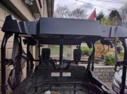
Well I finally got the new mount for my light bar built, and all the lights mountedl Took some pics for reference.

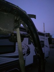
Started with a cardboard template, then cut these 2 plates out of some 1/4" mild steel plate with the bandsaw and grinder, then drilled.
IMG 20170417 133503 zpsltbrcfhd

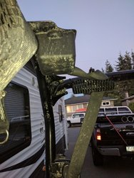
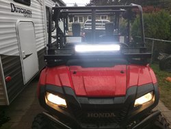
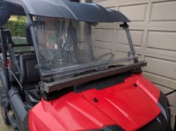
Took a chunk of 2x2x3/32 square tubing and tacked between the brackets, here's a fit up test before welding and drilling for the light.
IMG 20170417 140728 zpsdsembjaa

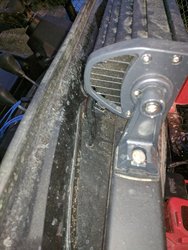
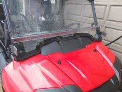
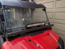
Light mounted. still can open the front window a bit, and can still add on a front rack later on if i want.
IMG 20170417 145348 zps9rwkh385

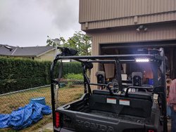
Rear floods mounted.
IMG 20170417 152002 zpsuul6kzqc

Have to pickup another fuse block as I used the one I had earmarked for this project on the boat last week, will post more updates as I progress.

Where has everyone else ran the wiring for rear lights? I was thinking down and under all the way up to under the front hood, but am open to suggestions.

Cheers
 
SuperYeti

SuperYeti

Well-Known Member
May 11, 2015
220
375
63
Vancouver, BC
Ownership

  1. 700-4
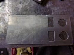
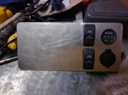
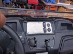
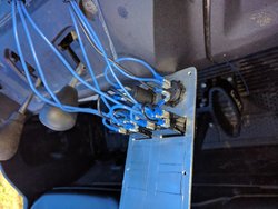
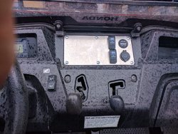
Finally got some more time to work on the lighting today, got the switch plate laid out a while ago, finally got everything cut and installed. Think i might go with a burnished or brushed finish on the aluminum, but all roughed in and mounted, and ready for final wiring.

IMG 20170619 160005 zpsj29pxloy

IMG 20170619 160248 zpsdkhyyrmj

IMG 20170619 164758 zpsyuvk7bad
 
SuperYeti

SuperYeti

Well-Known Member
May 11, 2015
220
375
63
Vancouver, BC
Ownership

  1. 700-4
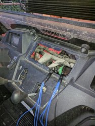
Well finally made some more progress. Got all the wiring fished through the ROPS to all the rear lights, and got everything routed into the dash. I need to pickup a few more parts to finish, as I had to steal a few things from what I had put aside for fixing the wiring on my TT this spring, and finish running the feeder cables to the battery, then I'm ready to finish the installation.

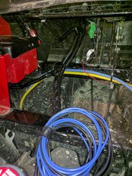
Here's the wiring going to the rear driver side light. I ran everything up the passenger side of the ROPS, then ran across to the driver side rear light.
IMG 20170827 202350

Here's the passenger side rear light wiring.
IMG 20170827 202332

Here's the front light bar, and where I entered the wiring with a grommet for that "factory look"
IMG 20170827 202402

Here's all the wiring coming out of the front of the passenger side ROPS
IMG 20170827 202258

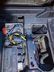
Everything sticking out of the dash ready to be wired.
IMG 20170827 202309

Everything tied neatly together, ready for mounting of fuse panel, relays etc.
IMG 20170827 202244

So the only thing I'm having an issue with is finding a diagram or picture where I'm supposed to be plugging in the accessory harness to get a clean switched power feed to turn on my relays. Any assistance or suggestions on that would be great.

Will post more as I get closer to completion.
 
Deluxe700

Deluxe700

Well-Known Member
Lifetime Member
Jul 2, 2017
856
1,101
93
Central Arkansas
Ownership

  1. 700-2
The accessory sub harness for the P700 plugs into the 12v accessory plug under the hood. With that harness all plugged in, you have your "key on" wires . I used it on my P700..
 
  • Like
Reactions: JimmyA and swsebek
SuperYeti

SuperYeti

Well-Known Member
May 11, 2015
220
375
63
Vancouver, BC
Ownership

  1. 700-4
Oh, so it's always taken up, because as far as I know, they all come with the 12v plug in the dash? That would explain why the dealership used one of those crap vampire taps for power to the winch switch which they installed in the worst place ever... You can see the red wire coming up there in the pictures.
 
Deluxe700

Deluxe700

Well-Known Member
Lifetime Member
Jul 2, 2017
856
1,101
93
Central Arkansas
Ownership

  1. 700-2
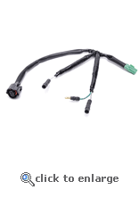
Here is a Pic of the accessory sub harness... one end plugs into the 12v accessory plug wire and the other end plugs into where the 12v accessory plug that you just pulled off to put the other end on. So , it just "taps" into the circuit, but in a "clean way". Then you have the pigtails with bullet connectors to attach your key on accessories....
Hope that helps...
Honda pioneer 700 2 seater accessory sub harness 20
 
Harman24630

Harman24630

Well-Known Member
Mar 24, 2016
283
493
63
Tazewell Va
Ownership

  1. 700-4
I cut mine on the plug side (not the main harness) soldered it back with another wire and heat shrank it back, I then ran that wire to the coil side of a relay. This way all I have to do to add something that's on with the key is pick it up off the relay and there isn't any extra load on factory wiring and I still have full use of the 12v plug.

IMG 0875
 
  • Like
Reactions: eastenn
SuperYeti

SuperYeti

Well-Known Member
May 11, 2015
220
375
63
Vancouver, BC
Ownership

  1. 700-4
Here is a Pic of the accessory sub harness... one end plugs into the 12v accessory plug wire and the other end plugs into where the 12v accessory plug that you just pulled off to put the other end on. So , it just "taps" into the circuit, but in a "clean way". Then you have the pigtails with bullet connectors to attach your key on accessories....
Hope that helps...
View attachment 53432

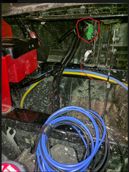
Yes, I have that harness, I could only find somewhere to plugin the green end, and it already had something plugged into it, I'll have to take another look tomorrow.

You can see I circled here in red, that something is plugged in, and seems to be going to the lighter socket. Am I right to assume that the accessory harness is already present, and I'll have to take power off that lighter socket to trigger my relay? I have 1x40A relays, and 4AWG wire I'm going to be running back to the battery. My thought was later, I can then mount another battery under the hood, and run all accessories off that, with an isolator between it and the main starting battery.

Untitled
 
  • Like
Reactions: swsebek
ohanacreek

ohanacreek

My EcoBoost has I4WD
Moderator
Lifetime Member
Jul 25, 2013
11,346
32,050
113
Shelby County, Alabama
Ownership

  1. 1000-5
Unplug the 12v outlet under the dash and plug the accessory harness in between
 
  • Like
Reactions: swsebek
advertisement
SuperYeti

SuperYeti

Well-Known Member
May 11, 2015
220
375
63
Vancouver, BC
Ownership

  1. 700-4
Unplug the 12v outlet under the dash and plug the accessory harness in between
That's what I thought, but it seemed like only 1 end of the harness fit. It was getting dark while I was trying, I'll have to take a look at it again.

EDIT: I re-read what you wrote, I see what you mean now, awesome thanks.
 
Last edited:
SuperYeti

SuperYeti

Well-Known Member
May 11, 2015
220
375
63
Vancouver, BC
Ownership

  1. 700-4
Boy do I feel dumb now lol. I checked last night, and see how it's supposed to be wired in. Kinda choked that the dealership didn't use the correct harness, and just cut into the 12v outlet harness when wiring in my winch, but all wired in, now i can finish the rest of my wiring. Thanks @ohanacreek! More updates to come as I progress.
 
SuperYeti

SuperYeti

Well-Known Member
May 11, 2015
220
375
63
Vancouver, BC
Ownership

  1. 700-4
FINALLY DONE!

Got everything done last night, looking good.

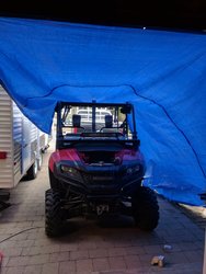
Of course it decided to start raining almost immediately after I started, a few minutes later, and I had a Pioneer grown up fort to play in!
IMG 20170917 130327

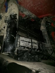
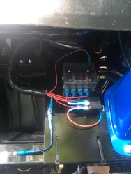
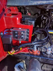
Finished up getting the main power wires pulled back to the battery, following the other ones the dealership ran for the winch. Got the relay, fuse panel, and all wiring tied up, and cleaned up, looking good! I also used 1 positive and 1 negative lug mounted to the sub frame there, giving me easy access for using the portal air compressor, giving jump starts etc. Panel is rated for 100a overall, 25a per circuit, I'm only using 3, 1 for the front light, 1 for the rear lights, and 1 for the USB chargers/volt meter. I ran all 6awg wire back to the batter, so am over-rated on the wire size, and have an 80a relay. It was a 5 wire relay, but I didn't need the normally closed pin so I de-pinned the harness for it so I didn't have extra wires laying around.
IMG 20170917 150608

Here's the battery side. You can see before I enter the battery compartment, I have an 80a resettable breaker there, to ensure if there are ever any shorts running up to the front I don't start a fire. I have another 2 posts I was going to install in there to bring the 2 main battery cables to, but will wait until I do the second battery, and have a central point for all accessories, then just 1 set of leads going to each battery, with an isolator on the cranking battery side. Will wait until I need some more power, right now running all 3 lights, plus the OEM headlghts I'm still seeing 14.1v at idle, so lots of power left.
IMG 20170917 160014

Back of the switch panel. Used those little crimp spade connectors that have a second little tab for another connection there, and daisy chained what I could to keep it cleaner. Was fun figuring out how all the indicator lights, and switches worked, as they came with no documentation. But in the end figured it out, and good to go. I turn the light indicator on whenever key'd power has the relay on, and then the on indicator lights up when the lights are turned on. Didn't see the need to only turn on the indicators when the headlights and dash lights are on.
IMG 20170917 171153

Panel all installed, everything wired up, ready to go
IMG 20170917 172509

Front light testing while it was still light out
IMG 20170917 172108

Rear flood lights
IMG 20170917 172058

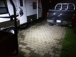
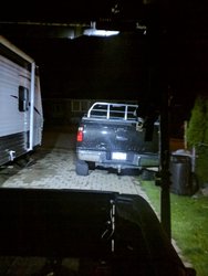
Here's some shots of the floods at night, they give out great light, and should be sufficient
IMG 20170917 211619
IMG 20170917 211607

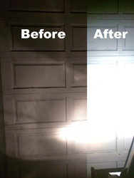
This pic was a bit hard to do, because my camera was adjusting for the increased light, but i used PS, and upped the exposure to show a similar output from the OEM headlights, and gives a pretty good idea how bright it actually was. I may need to repoint the lights a bit further up once I get out and test in the bush, we'll see.
IMG 20170917 212404 merged
 
  • Like
Reactions: Bowhunter
SuperYeti

SuperYeti

Well-Known Member
May 11, 2015
220
375
63
Vancouver, BC
Ownership

  1. 700-4
Quick update, got the rig loaded up last night for hunting this weekend, and finally got a good test of the lights in open area. Ended up having to re-point the front light a bit higher after this picture, but it's throwing PLENTY of light.

IMG 20170922 210100


IMG 20170922 210053
 
SuperYeti

SuperYeti

Well-Known Member
May 11, 2015
220
375
63
Vancouver, BC
Ownership

  1. 700-4
Sweet! My RAM mount showed up yesterday and got it installed, figured out how to get the tablet working nice with the backup camera and WiFi adapter for it, and can get them installed soon.

Here's the main mount installed. Got some proper screws and nuts to install the panel as well, the 2 middle ones were a PAIN to install, had to tape the nut and washer on to the wrench to get them up there, no plans to remove those for a LONG time lol.
IMG 20171002 181518


Here it is with the tablet installed. Nice and sturdy.
IMG 20171002 181630
 
  • Like
Reactions: Tflynn
Tramguage1

Tramguage1

Texan
Moderator
Lifetime Member
Supporting Member
Club Contributor
Jul 2, 2015
7,500
30,744
113
Somereset, Texas
Ownership

  1. 1000-5

  2. 1000 6 Crew

  3. Talon X

  4. Talon R4 LV
So you have a backup camera the works with your tablet? A little more info please. I use a Galaxy 8" tablet
 
SuperYeti

SuperYeti

Well-Known Member
May 11, 2015
220
375
63
Vancouver, BC
Ownership

  1. 700-4
So you have a backup camera the works with your tablet? A little more info please. I use a Galaxy 8" tablet

Yes, it's a standard backup camera, and it has a WiFi video converter. So it provides power to the camera, and then takes the RCA video output and encodes it with MJPEG, and broadcasts that via WiFi. The Wifi Adapter portion comes with an app that runs on Android, and probably iOS. I used a chunk of software called tasker to have it detect when the Wifi signal is present and turn on the camera software. My original plan was to use a USB board that I could attach to the reverse lights to trigger turning on the camera app, but my tablet only supports USB-OTG OR Charging, not both at the same time, so I used this as a workaround. It's not perfect, but good enough for now. It also goes back to home and closes the camera app when the wifi signal goes away.
 
swsebek

swsebek

Red,White And Blue Collar Soul
Lifetime Member
May 4, 2014
2,854
5,835
113
pa
Ownership

  1. 700-4
That is cool I didn't know I needed that till I seen It.:D
Does it work well off-road or at night backing up.
When I mounted the spare I lost a lot of rear view.
55 bucks is cheap if it's good
 
SuperYeti

SuperYeti

Well-Known Member
May 11, 2015
220
375
63
Vancouver, BC
Ownership

  1. 700-4
That is cool I didn't know I needed that till I seen It.:D
Does it work well off-road or at night backing up.
When I mounted the spare I lost a lot of rear view.
55 bucks is cheap if it's good

I haven't installed it yet. It took me a year to find the time to get all the lights, power distribution, etc installed and ready. I'm finally there, so probably next weekend I'll get it installed. From my testing in my lab it seems like it's going to work well. I have a big 2 gun bag I hang off the ROPS which brings my ability to view anything behind me down to zero, so it will be a nice addition. Eventually I'm also going to wire it so I can turn it on with a switch, or with the reverse lights using a couple diode's so I don't back feed either system, but for now it will be just based on the reverse switch.
 
  • Like
Reactions: swsebek
advertisement

About us

  • Our community has been around for many years and pride ourselves on offering unbiased, critical discussion among people of all different backgrounds. We are working every day to make sure our community is one of the best.

User Menu

Buy us a beer!

  • Lots of time and money has gone into making sure the community is running the best software, best designs, and all the other bells and whistles. Care to buy us a beer? We'd really appreciate it!

    Beer Fund!

    Club Membership!