You are using an out of date browser. It may not display this or other websites correctly.
You should upgrade or use an alternative browser.
You should upgrade or use an alternative browser.
ohanacreek
My EcoBoost has I4WD
Moderator
Lifetime Member
Has anyone had to change a stater to charge the Dual batteries
Nope
D
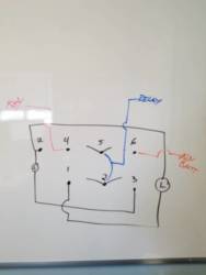
If you wire it like this, with 1 and 6 jumped, isn't the aux battery going to backfeed your key power? I cannot see how it wouldn't.I will try to help.
First. This is the switch i got.
Ancor 554033 Marine Grade Electrical Sealed Rocker Switch (Double Pole/Double Throw, Constant On / Con... https://www.amazon.com/dp/B000NI5ENM?tag=sxsweb24-20
It is a 3 way switch with on, off, on. My goal was to set it up like dragon did. On one way turned all my accessories on and off with the key while on the other way turned them on and kept them on no matter the key position.
Basically what this switch does is control power to the solenoid that is between the battery and the fuse panal. When the solenoid has power it allows power through to the fuse panal. When it does not have power it stops the power at the solenoid and does not allow it through to the panal.
You will also need one of these jumpers. It will make your life easier. I will explain later on.
MICTUNING 5 Pin Rocker Switch Wire Set With Male/ Female Terminal https://www.amazon.com/dp/B00SAH1J8M/?tag=sxsweb24-20
So let's start with the switch and wires. You will need 3 wires that come to your switch. One will come directly from your second battery. I would suggest putting a inline fuse in this wire. I used 15a. Second wire will come from a keyed hot wire. I took this off the black and white wire under the accessory fuse. It was the 5th fuse from the top on my 18 LE. There is a very good thread on how to find it on here. The last wire you will need going to the switch is the wire that will go to the solenoid.
So now we have 3 wires run to our switch.
A. From second battery
B. Keyed power
C. Out to solenoid.
The back of our switch has 6 male pins. I will number them for the sake of this discussion. I don't think they are labeled on the switch but this would be the view if you flipped the switch over. The top and bottom of a switch like this don't really matter.
1 2
3 4
5 6
So now we simply hook up our wires.
First take your jumper and hook up the two female ends to number 1 and 6. Then take the end that comes off the jumper and hook it up to wire C which goes out to the solenoid. Take wire A and hook that to 3 and hook B to 4.
It took me a little bit to figure this out so hopefully it helps some people here. My father is an electrician and it took a few FaceTime calls to him also, but mine now works exactly how I want it.
Didn't mean to jump in your thread Dragon, please let me know if you did it differently.
Edit: I did not ground my switch since I do not have any lights in mine. If you have lights you will need one additional ground wire to complete the circuit so the lights will illuminate.
Sent from my SM-N950U using Tapatalk
If you wire it like this, with 1 and 6 jumped, isn't the aux battery going to backfeed your key power? I cannot see how it wouldn't.
Sent from my SM-N950U using Tapatalk
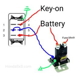
EDIT NOTE: This diagram is NOT correct.
I made this diagram because I am about to make the dual battery modification. I had to dumb it down to my level of understanding: a DPDT switch is basically two separate 3-position switches operated by the same rocker. This is only detailing the switch portion of the install. There will be an isolator between batteries, a circuit breaker between the aux battery and solenoid, and more detail on the ground points as well.
ON - When switch up to key on battery:
3 powers 1
4 powers 2
3 disconnected 5
4 disconnected 6
Therefore "key on" power is opening the solenoid and aux panel is powered from aux batt
1 cannot back feed 6 into 4 because there is no connection between 6 and 4 when switch in the up or opposite direction
OFF - When switched to center or off:
3 disconnected 1
4 disconnected 2
3 disconnected 5
4 disconnected 6
No power to the solenoid, it remains closed and does not power the Aux Panel, Aux Panel is completely off
ON - When switched down to auxiliary battery:
3 disconnected 1
4 disconnected 2
3 powers 5
4 powers 6
Power from aux batt opens solenoid whether key is on or off. Aux panel is powered by aux batt.
Disclaimer: I am not an electrician nor do I play one on TV, nor did I stay at a Holiday Inn Express last night. Please let me know if I am wrong about anything I just posted because that's how I plan on wiring my ride. I'd also like to change it for others. Nobody likes incorrect diagrams.
Thanks!
John
Last edited:
Neohio
Beast of the East
Lifetime Member
Supporting Member
Club Contributor
D
Correct, unless the switch has a built in lighting circuit. With a lighting circuit there is a ground (pin 7) and light powers from pins 1 and 3. With the jumper from 1 to 6 and the switch in the aux battery position, pins 1, 6, and 3 are seeing 12V. This will back feed power to the key power circuit.I made this diagram because I am about to make the dual battery modification. I had to dumb it down to my level of understanding: a DPDT switch is basically two separate 3-position switches operated by the same rocker. This is only detailing the switch portion of the install. There will be an isolator between batteries, a circuit breaker between the aux battery and solenoid, and more detail on the ground points as well.
View attachment 62355
ON - When switch up to key on battery:
3 powers 1
4 powers 2
3 disconnected 5
4 disconnected 6
Therefore "key on" power is opening the solenoid and aux panel is powered from aux batt
1 cannot back feed 6 into 4 because there is no connection between 6 and 4 when switch in the up or opposite direction
OFF - When switched to center or off:
3 disconnected 1
4 disconnected 2
3 disconnected 5
4 disconnected 6
No power to the solenoid, it remains closed and does not power the Aux Panel, Aux Panel is completely off
ON - When switched down to auxiliary battery:
3 disconnected 1
4 disconnected 2
3 powers 5
4 powers 6
Power from aux batt opens solenoid whether key is on or off. Aux panel is powered by aux batt.
Disclaimer: I am not an electrician nor do I play one on TV, nor did I stay at a Holiday Inn Express last night. Please let me know if I am wrong about anything I just posted because that's how I plan on wiring my ride. I'd also like to change it for others. Nobody likes incorrect diagrams.
Thanks!
John

Sent from my SM-N950U using Tapatalk
John @OnTheJob
Would you mind providing a link to the switch you used?
I did not take into account a lighting pin and it does appear the one I plan on using does have the 7th pin.
The switch I will be using:
AOB on-off-on rocker
Rocker switch 589B2 12V MAIN AUX on off on blue ATV UTV RTV DPDT | eBay
Dragon21
In my defense, I was left unsupervised
Lifetime Member
advertisement
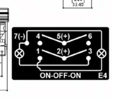
This should be the wiring for that switch:
1- Not used
2/5- Jumpered and goes to power solenoid
4- Input power (Key or 2nd battery)
6- input power (Key or 2nd battery)
3- not used
7- ground
Excuse my electrical ignorance but are pins on the back of the switch numbered:
1 2
3 4
5 6
7
or
1 4
2 5
3 6
7
I just finished my preliminary install and I'm wiring the switch next.
Dragon21
In my defense, I was left unsupervised
Lifetime Member
S
Ok so I Just purchased everything in your video and I think I understand most of it but I have a couple of questions....the 4 rocker switch panel I ordered on amazon have a lot of jumpers on them daisy chaining them together which is confusing me. They are 5 pole It looks like the black and yellow are ground and red is hot but there is also a blue wire, I tested red and blue on my fuse block and noticed that the blue leds on switch were lit all the time, didn't even turn key on. Do I just tie all those looped blue on switches to an accessory wire? Like white/black that I tied my winch to? Also The winch in/out switch is 7 pole not sure how to wire this one.....last question is what is the white plate the fuse panel is mounted on and what size radiator hose? Sorry for all the questions just want to make sure I wire this properly the first time, I am using 52" light bar, 2 cube rear lights, radio/Bluetooth, and winch hence the 4 gang switch plate....the 5th switch is for the solenoid which I noticed you grounded to fuse block and then it looks like red wire goes to that rocker switch which is 5 pole what all would be hooked up on that one?So how to videos are not really my thing. But i gave it a shot. If i misspoke let me know. Thanks to a bunch of people on this forum for helping me, especially with the DPDT switch/ solenoid idea.
Dragon21
In my defense, I was left unsupervised
Lifetime Member
gonna need pictures of your switch panel wiring. Im assuming when you are mentioning the yellow and blue wires, thats the winch solenoid. Yellow and Blue go to the winch, red to power and black to ground. White plate is just some delrin, you can cut some cutting board and do the same thing. I think the radiator hose part number is in the video description.Ok so I Just purchased everything in your video and I think I understand most of it but I have a couple of questions....the 4 rocker switch panel I ordered on amazon have a lot of jumpers on them daisy chaining them together which is confusing me. They are 5 pole It looks like the black and yellow are ground and red is hot but there is also a blue wire, I tested red and blue on my fuse block and noticed that the blue leds on switch were lit all the time, didn't even turn key on. Do I just tie all those looped blue on switches to an accessory wire? Like white/black that I tied my winch to? Also The winch in/out switch is 7 pole not sure how to wire this one.....last question is what is the white plate the fuse panel is mounted on and what size radiator hose? Sorry for all the questions just want to make sure I wire this properly the first time, I am using 52" light bar, 2 cube rear lights, radio/Bluetooth, and winch hence the 4 gang switch plate....the 5th switch is for the solenoid which I noticed you grounded to fuse block and then it looks like red wire goes to that rocker switch which is 5 pole what all would be hooked up on that one?
F
I liked your setup so much, i decided to copy it. Here's my problem: I screwed with a 7-pin DPDT switch (with the LED's, just like yours) and I couldn't' get the LEDs on the switch to light correctly. Any chance you can help here, perhaps show the back of that switch wiring? I was wondering if i had a faulty switch.This should be the wiring for that switch:
1- Not used
2/5- Jumpered and goes to power solenoid
4- Input power (Key or 2nd battery)
6- input power (Key or 2nd battery)
3- not used
7- ground
Hondasxs
Club Founder
Staff member
Lifetime Member
Supporting Member
Can you give any info on your switch?I liked your setup so much, i decided to copy it. Here's my problem: I screwed with a 7-pin DPDT switch (with the LED's, just like yours) and I couldn't' get the LEDs on the switch to light correctly. Any chance you can help here, perhaps show the back of that switch wiring? I was wondering if i had a faulty switch.
Link? or wiring layout?
There are several designs and dont expect all 7 pin switches are the same.
F
Here's a link. It's a DPDT rocker, 7 pin. Amazon.com: HYY 12v/24v Waterproof 7 Pins 2 RED LED Light On-Off-on Marine Boat Dpdt Rocker Switch: Automotive

Hondasxs
Club Founder
Staff member
Lifetime Member
Supporting Member
F
yea, that's the first thing i tried. I think my switch is bad. When i wire the 2 and 5 together, the LED on the switch stays on. I'm trying a new switch. i appreicate the response so quickly!
Similar threads
- Replies
- 8
- Views
- 588
C
- Replies
- 7
- Views
- 970
J
- Replies
- 11
- Views
- 1K
J
- Replies
- 13
- Views
- 1K
P


