You are using an out of date browser. It may not display this or other websites correctly.
You should upgrade or use an alternative browser.
You should upgrade or use an alternative browser.
nitzo
Well-Known Member
Lifetime Member
I have a couple more drawings for ya'll to look at. Just think when you guys get done with me we will have a setup that anybody can build. Lol.
First picture is just a blank, I know how some of you can edit/draw on attachments, I included this for that. Remember, I'll take any and all help I can get.
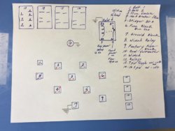
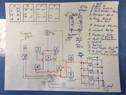
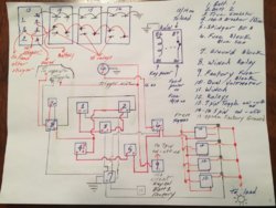
The second one is the way I have or am going to wire my ride. If you see anything that might be wrong please please let me know. I didn't include any wiring on the top of the page( the switches) as I'm still out on that, I just don't get it........Again, any help will be appreciated.
First picture is just a blank, I know how some of you can edit/draw on attachments, I included this for that. Remember, I'll take any and all help I can get.

The second one is the way I have or am going to wire my ride. If you see anything that might be wrong please please let me know. I didn't include any wiring on the top of the page( the switches) as I'm still out on that, I just don't get it........Again, any help will be appreciated.

Hondasxs
Club Founder
Staff member
Lifetime Member
Supporting Member
Hondasxs
Club Founder
Staff member
Lifetime Member
Supporting Member
Let's tall about the #8 the winch relay. Something is not right.
The main lines should be direct to the #2 battery.
Looks like you have it off the stinger. Thats incorrect. Your winch can pull upwards of 300 amps.
Some winches have a high amp resetable fuse. I removed mine.
Then you should have..
The 12v+ trigger wire, I recomend a key-on source. You should always run your motor anyways.
And you have the 2 reverseable control lines. This may be built into a handheld remote.
Sent from my SM-G955U using Tapatalk
Last edited:
Hondasxs
Club Founder
Staff member
Lifetime Member
Supporting Member
I would also move the lower volt meter pin to after the stinger. That way both are on a switched source.
Item #9 [key on 15a] should go to the on/off/on switch and not to the stinger.
Leave the volt#1 hooked up to it.
Item #9 [key on 15a] should go to the on/off/on switch and not to the stinger.
Leave the volt#1 hooked up to it.
nitzo
Well-Known Member
Lifetime Member
Update. Made a change for stinger usage to fuse protect the panel. View attachment 156782
Sent from my SM-G955U using Tapatalk
WOW. You rock. Thank-you, Thank-you, Thank-you. This is just what I have been looking for. We are going to be spending the week up in Milledgeville, GA for the Thunder Ralley so I won't get any work done on the pioneer but I'll hit it hard when we get back.
Again, I appreciate all the help and replies.
nitzo
Well-Known Member
Lifetime Member
Let's tall about the #8 the winch relay. Something is not right.
The main lines should be direct to the #2 battery.
Looks like you have it off the stinger. Thats incorrect. Your winch can pull upwards of 300 amps.
Sent from my SM-G955U using Tapatalk
I kind of understand this but what if something happens to the winch relay and it's connected directly to the battery? I have no protection.
Hondasxs
Club Founder
Staff member
Lifetime Member
Supporting Member
Do you mean short circut or roge operation?I kind of understand this but what if something happens to the winch relay and it's connected directly to the battery? I have no protection.
Short circut - the required operation amps is in the 300 range. You can install a 300+ fuse link but need to research max amps. Possibility of your winch overdrawing and shutting off when you need it the most is very likley. Thus why many dont install them.
Roge operation - this is more a concern coming from the control wires than the main lines. Thus why I recomend that being key on only. Its unlikely the contactor will "stick" without those lines being energized.
Keep in mind the starter in every vehecial you own is set up just like this. Direct to the battery with a contactor in between. The "starter" fuse you may find is for the control lines and not the actual starter.
Hooking up like you have it in your design will blow both the stinger and the 100a fuse.
Here is the common layout.
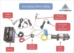
Sent from my SM-G955U using Tapatalk
Last edited:
nitzo
Well-Known Member
Lifetime Member
Do you mean short circut or roge operation?
Short circut - the required operation amps is in the 300 range. You can install a 300+ fuse link but need to research max amps. Possibility of your winch overdrawing and shutting off when you need it the most is very likley. Thus why many dont install them.
Roge operation - this is more a concern coming from the control wires than the main lines. Thus why I recomend that being key on only. Its unlikely the contactor will "stick" without those lines being energized.
Keep in mind the starter in every vehecial you own is set up just like this. Direct to the battery with a contactor in between. The "starter" fuse you may find is for the control lines and not the actual starter.
Hooking up like you have it in your design will blow both the stinger and the 100a fuse.
Awesome. Thanks again. I'm going to make the corrections to my diagram and I'll post it again. Maybe ya'll can give it one final run thru before the build. I know this is all going help numerous folks, one is my brother, he is doing the same thing to his 18' 1000.
Hondasxs
Club Founder
Staff member
Lifetime Member
Supporting Member
Update again.
I made a on/off/on switch for a client tonight and I realized I had the pins reversed for the lights to work correctly.
The following gives the top or bottom light on for whichever way the switch is flipped.
So key-on. The bottom would be on.
Battery the top would be on.
Middle OFF no lights.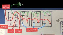
Sent from my SM-G955U using Tapatalk
I made a on/off/on switch for a client tonight and I realized I had the pins reversed for the lights to work correctly.
The following gives the top or bottom light on for whichever way the switch is flipped.
So key-on. The bottom would be on.
Battery the top would be on.
Middle OFF no lights.

Sent from my SM-G955U using Tapatalk
Last edited:
advertisement
nitzo
Well-Known Member
Lifetime Member
Update again.
I made a on/off/on switch for a client tonight and I realized I had the pins reversed for the lights to work correctly.
The following gives the top or bottom light on for whichever way the switch is flipped.
So key-on. The bottom would be on.
Battery the top would be on.
Middle OFF no lights. View attachment 156996
Sent from my SM-G955U using Tapatalk
When you say "5a fused after the stinger", you mean any circuit after the stinger. And "to stinger" is the small wire that powers it? Also, the 7 pin on-off-on switch I have has a permanent jumper b/t the 2 and 5, that needs to be removed, correct?
Last edited:
Hondasxs
Club Founder
Staff member
Lifetime Member
Supporting Member
I think it's getting close.
Few changes.
I can photoshop them 4 u later after lunch.
Most has to do with the winch layout.
Do u plan to have a winch dash switch?
Also by "5a fused after stinger" I mean.
The stinger sends power to the fuse block from the block add a 5a fuse called "pannel" that protects it. I feel this is important because if a wire comes unhooked that's where it is most likley to occur seeing there will be umpteen connections.
Sent from my SM-G955U using Tapatalk
nitzo
Well-Known Member
Lifetime Member
I think it's getting close.
Few changes.
I can photoshop them 4 u later after lunch.
Most has to do with the winch layout.
Do u plan to have a winch dash switch?
Yes I do, I have another dpdt 7 pin that came pre-wired with the KFI Stealth 4500 winch.
by "5a fused after stinger" I mean.
The stinger sends power to the fuse block from the block add a 5a fuse called "pannel" that protects it. I feel this is important because if a wire comes unhooked that's where it is most likley to occur seeing there will be umpteen connections.
Right, so after I take a big wire(using #4 cu) from the stinger to power the blue sea fuse block, I'll take one of the circuits (fused at 5 amps) from the fuse block to the main dpdt 7 pin on my dash panel.
I looks like the #5 pin on this switch(7 pin dpdt) powers the stinger to close, then we get power back to the switch via the stinger to fuse block (5a fuse) to #2 pin on the dash 7 pin switch. WHEW!!!!!
Hondasxs
Club Founder
Staff member
Lifetime Member
Supporting Member
Changes to winch layout.
Still needs a good review.
Also, I assume the relays all have their own fuse? and NOT a single line?
Is the same with the relay grounds?
You can combine the grounds as long as the wire size gets increased too, But most run lines back to the ground buss.

Still needs a good review.
Also, I assume the relays all have their own fuse? and NOT a single line?
Is the same with the relay grounds?
You can combine the grounds as long as the wire size gets increased too, But most run lines back to the ground buss.
nitzo
Well-Known Member
Lifetime Member
Not sure what you mean by this.Still needs a good review.
Yes, I drew that wrong, each relay will have its own circuit coming off the fused blue sea fuse panel running to the "30" pin on the relay.I assume the relays all have their own fuse? and NOT a single line?
I was going to run just one run of 14 cu from the "86" pin to the grd buss bar, but I can double it up or even run each its own.Is the same with the relay grounds.
You can combine the grounds as long as the wire size gets increased too, But most run lines back to the ground buss.
As I have said, your help is great. Thanks so much.
Last edited:
Hondasxs
Club Founder
Staff member
Lifetime Member
Supporting Member
Still needs good review - Meaning we just need to look over the layout few more times.
Yes, consider running each ground back to the buss bar.
You can combine, but ensure the wire size is adequate for the combined load.
Yes, consider running each ground back to the buss bar.
You can combine, but ensure the wire size is adequate for the combined load.
ohanacreek
My EcoBoost has I4WD
Moderator
Lifetime Member
It LOOKS right, 10&11 are missing numbers don’t line up on toggles but I get the intent. “To Toggles” should be “from toggles” and Red since it should be a positive feed from the toggles to activate the relays based on the relay wiring you have shown. I did not double check the pin layouts of the switches as they can vary slightly manufacturer to manufacture especially with the Amazon Special. But it looks like a standard carling layout.Still needs good review - Meaning we just need to look over the layout few more times.
Yes, consider running each ground back to the buss bar.
You can combine, but ensure the wire size is adequate for the combined load.
nitzo
Well-Known Member
Lifetime Member
It LOOKS right, “To Toggles” should be “from toggles” and Red since it should be a positive feed from the toggles to activate the relays based on the relay wiring you have shown. I did not double check the pin layouts of the switches as they can vary slightly manufacturer to manufacture especially with the Amazon Special. But it looks like a standard carling layout.
Yes, you are right, I should also have the "87" to load pin in red.
nitzo
Well-Known Member
Lifetime Member
Still needs good review - Meaning we just need to look over the layout few more times.
Ok ya'll, I'm back from vacation and ready to dig into this. If you guys would, please take a final look and I'll go ahead and start.
Again, thanks so much for your help. I'll keep you posted as I go along.
I almost forgot:
Also, the 7 pin on-off-on switch I have has a permanent jumper b/t the 2 and 5, that needs to be removed, correct?
advertisement
Similar threads
P
- Replies
- 16
- Views
- 1K
P
- Replies
- 8
- Views
- 1K
T
- Replies
- 3
- Views
- 915
N
- Replies
- 8
- Views
- 1K
J
- Replies
- 11
- Views
- 2K

