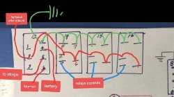
P1000 Dual Batterys and a horse with no legs

Hondasxs

Hondasxs

Club Founder
Staff member
Lifetime Member
Supporting Member
Feb 13, 2013
18,511
67,231
113
Charlotte, NC
HondaSxS.com
Ownership

  1. 1000-5

  2. Talon R
Its fixable.
Mess with it in a few. But with the exception of the winch contactor wires it looks good.

Sent from my SM-G955U using Tapatalk
 
nitzo

nitzo

Well-Known Member
Lifetime Member
Aug 16, 2019
521
1,105
93
East Coast, Florida
Ownership

  1. 1000-5
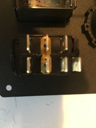
Also, the 7 pin on-off-on switch I have has a permanent jumper b/t the 2 and 5, that needs to be removed, correct?

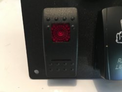
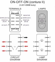
This is the switch:
Carling Technologies Sealed Lighted Rocker Switch DPDT 7 Connections w/Rocker Actuator Red Lens

Switch1 Switch2 Switch3
 
Hondasxs

Hondasxs

Club Founder
Staff member
Lifetime Member
Supporting Member
Feb 13, 2013
18,511
67,231
113
Charlotte, NC
HondaSxS.com
Ownership

  1. 1000-5

  2. Talon R
I need some of those jumpers.

Yes. Removed it.

Sent from my SM-G955U using Tapatalk
 
Hondasxs

Hondasxs

Club Founder
Staff member
Lifetime Member
Supporting Member
Feb 13, 2013
18,511
67,231
113
Charlotte, NC
HondaSxS.com
Ownership

  1. 1000-5

  2. Talon R
I need to find a bunch of those jumpers. Does anyone know where to get them?
 
nitzo

nitzo

Well-Known Member
Lifetime Member
Aug 16, 2019
521
1,105
93
East Coast, Florida
Ownership

  1. 1000-5
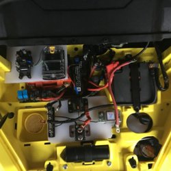
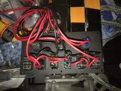
Coming right along on the build. I'm taking my time, only working a couple hours a day on the weekends, trying to keep this a fun project instead of a "must get it done" job.

New New2
 
Last edited:
  • Like
Reactions: TripleB
nitzo

nitzo

Well-Known Member
Lifetime Member
Aug 16, 2019
521
1,105
93
East Coast, Florida
Ownership

  1. 1000-5
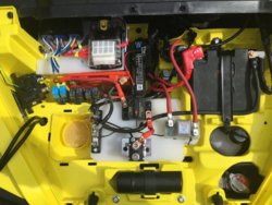
A tad more done today. I got the blue sea fuse panel and the relays mounted.
I also decided on the location for the winch relay. The winch is pretty much self contained all I'm doing is providing power to it, all the controls, switches are pre-wired and I'm going with that.
New1
 
nitzo

nitzo

Well-Known Member
Lifetime Member
Aug 16, 2019
521
1,105
93
East Coast, Florida
Ownership

  1. 1000-5
Well, I got it all together this afternoon. I'll post pics when I get all the wires routed right and tie wrapped. I'm pleased with the set-up, it was a lot of work but worth it. So far I only have one issue and I'll have to trace it down and figure it out. The dual volt meters aren't working correctly. I'm getting the same reading on both meters. I'm not sure which one it's reading but it's the same, Batt 1 or 2, I'm not sure, I ran out of time.

Ya'll's help was and is appreciated
 
ehart814

ehart814

Well-Known Member
Lifetime Member
Club Contributor
Mar 28, 2016
1,655
3,645
113
NWPA
Ownership

  1. 500

  2. 1000-5
Well, I got it all together this afternoon. I'll post pics when I get all the wires routed right and tie wrapped. I'm pleased with the set-up, it was a lot of work but worth it. So far I only have one issue and I'll have to trace it down and figure it out. The dual volt meters aren't working correctly. I'm getting the same reading on both meters. I'm not sure which one it's reading but it's the same, Batt 1 or 2, I'm not sure, I ran out of time.

Ya'll's help was and is appreciated

I had to switch the blue and green wire because they read backwards. I don’t think I made a mistake but it’s fixed. I would double check that those connections on the back of the gauge aren’t shorting to each other. They are way too close together I think.


Sent from my iPhone using Tapatalk
 
nitzo

nitzo

Well-Known Member
Lifetime Member
Aug 16, 2019
521
1,105
93
East Coast, Florida
Ownership

  1. 1000-5
They are way too close together I think.

I agree 100%.

I have it fixed now. What I originally did was try and reserve space and put different low amperage circuits together into one circuit. Well I separated everything and now they (the volt meters) each read as they should. I guess I just had to much going and had to backup a bit and figure it out.

One thing, maybe someone can explain this to me: When I start the machine for a brief second on voltmeter 1 I will see maybe 11 or 12 volts, as soon as it starts vm1(voltmeter 1) will read 14 volts, volt meter 2 (vm2) will read 12 volts maybe, then within maybe 2 or 3 seconds will climb to 14 volts like vm1, both meters will stay the same from then on. Now, if I hit my winch, both meters will drop to say 13.3 then with in 2 seconds or so climb back to 14. Can someone tell me what exactly is taking place? I get the voltage climbing, I know its charging, but why the meters read what they do, I have no clue.

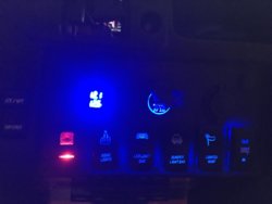
Also done tonight, light bar installed and working:
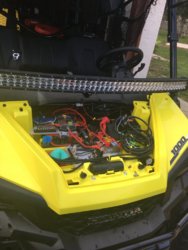
Lightbar


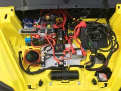
Wiring is done, I just have to tidy it all up. I'm not sure what to do with those winch wires, I've cut a few and made them fit, I guess I'll have to do the rest, they really make it look ugly with them being so long and all.
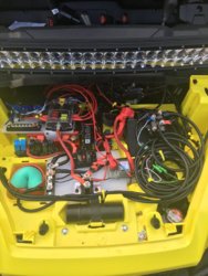
New3
 
advertisement
Hondasxs

Hondasxs

Club Founder
Staff member
Lifetime Member
Supporting Member
Feb 13, 2013
18,511
67,231
113
Charlotte, NC
HondaSxS.com
Ownership

  1. 1000-5

  2. Talon R
When the blue light is "on" both batteries are combined. Therefore they will read the same in most cases. Especially if you are reading from the isolator bolts.

The mark is 12.8v. Above that they will be same or very close. Below that they are separated and will read very different.

Cranking the primary will drop until running. Secondary may also pull down some, until it disconnects.


Sent from my SM-G955U using Tapatalk
 
Hondasxs

Hondasxs

Club Founder
Staff member
Lifetime Member
Supporting Member
Feb 13, 2013
18,511
67,231
113
Charlotte, NC
HondaSxS.com
Ownership

  1. 1000-5

  2. Talon R
Wiring is done, I just have to tidy it all up. I'm not sure what to do with those winch wires, I've cut a few and made them fit, I guess I'll have to do the rest, they really make it look ugly with them being so long and all.

Yes. You need to remove all that coiled up wire. Otherwise it will create an inductive effect and could cause problems. Especially being large guage.
 
Last edited:
nitzo

nitzo

Well-Known Member
Lifetime Member
Aug 16, 2019
521
1,105
93
East Coast, Florida
Ownership

  1. 1000-5
Yes. You need to remove all that coiled up wire. Otherwise it will create an inductive effect and could cause problems. Especially being large guage.

Wow, I didn't even think of that. I've hooked up thousands of transformers, I should have seen that.

Thanks .
 
ehart814

ehart814

Well-Known Member
Lifetime Member
Club Contributor
Mar 28, 2016
1,655
3,645
113
NWPA
Ownership

  1. 500

  2. 1000-5
This is the switch:
Carling Technologies Sealed Lighted Rocker Switch DPDT 7 Connections w/Rocker Actuator Red Lens

View attachment 158785 View attachment 158786 View attachment 158787

I am about to tackle this switch install.

I have my second battery, isolator kit, circuit breaker, stinger, and blue sea fuse box all installed. I just need to wire this switch in to have the option of key-off accessories.

So looking through the thread and I am still not sure about wiring that switch. I understand the jumper needs to be removed and then one of those posts is the key on power feed, and the other is positive from the battery. I can see the ground position. Other than that, I think the only other wire would be the output to trigger the stinger.

Anyhow, can someone show me exactly how to wire that switch to get it working right?
 
Hondasxs

Hondasxs

Club Founder
Staff member
Lifetime Member
Supporting Member
Feb 13, 2013
18,511
67,231
113
Charlotte, NC
HondaSxS.com
Ownership

  1. 1000-5

  2. Talon R
I am about to tackle this switch install.

I have my second battery, isolator kit, circuit breaker, stinger, and blue sea fuse box all installed. I just need to wire this switch in to have the option of key-off accessories.

So looking through the thread and I am still not sure about wiring that switch. I understand the jumper needs to be removed and then one of those posts is the key on power feed, and the other is positive from the battery. I can see the ground position. Other than that, I think the only other wire would be the output to trigger the stinger.

Anyhow, can someone show me exactly how to wire that switch to get it working right?
Post #13 is a example. Jumper is kept here.

Removing or keeping the jumper all depends on what you want to do with your setup.

Sent from my SM-G955U using Tapatalk
 
ehart814

ehart814

Well-Known Member
Lifetime Member
Club Contributor
Mar 28, 2016
1,655
3,645
113
NWPA
Ownership

  1. 500

  2. 1000-5
Well now I’m even more confused. I thought that if I wanted to have a key on position and an option to flip the switch the other way so that I can use the accessories with the key off, then I would need to remove the jumper and connect a key on power to one of the posts and a hot wire straight to the battery to the other post.


Sent from my iPhone using Tapatalk
 
ehart814

ehart814

Well-Known Member
Lifetime Member
Club Contributor
Mar 28, 2016
1,655
3,645
113
NWPA
Ownership

  1. 500

  2. 1000-5
Post #13 is a example. Jumper is kept here.

Removing or keeping the jumper all depends on what you want to do with your setup.

Sent from my SM-G955U using Tapatalk

Ok I looked at that post. My switch didn’t even come with the jumper so I guess I need to make one.


Sent from my iPhone using Tapatalk
 
Hondasxs

Hondasxs

Club Founder
Staff member
Lifetime Member
Supporting Member
Feb 13, 2013
18,511
67,231
113
Charlotte, NC
HondaSxS.com
Ownership

  1. 1000-5

  2. Talon R
All depends on your needs and how you want to do it. There are several ways and all are correct.

First. This whole thread has been based off a relay type system. Not a direct power system

This is one method I like since most people use a positive buss. This puts just the panel on a 5 amp fuse. 43d8eca449ad4447fbd4d8579d96ce8e

But if all your sources were fused already. Then using the jumper would be fine too I guess.


Sent from my SM-G955U using Tapatalk
 
nitzo

nitzo

Well-Known Member
Lifetime Member
Aug 16, 2019
521
1,105
93
East Coast, Florida
Ownership

  1. 1000-5
All depends on your needs and how you want to do it. There are several ways and all are correct.

First. This whole thread has been based off a relay type system. Not a direct power system

This is one method I like since most people use a positive buss. This puts just the panel on a 5 amp fuse. View attachment 163207

But if all your sources were fused already. Then using the jumper would be fine too I guess.

For what it's worth to anyone planning on doing the set-up I used. I put nearly 100 miles on some rough nasty trails this weekend and the wiring job worked perfectly, I have not single complaint.

I have to thank all the guys that gave me input, I would not have had a clues to how to do it if ya'll wouldn't have helped.
 
advertisement

About us

  • Our community has been around for many years and pride ourselves on offering unbiased, critical discussion among people of all different backgrounds. We are working every day to make sure our community is one of the best.

User Menu

Buy us a beer!

  • Lots of time and money has gone into making sure the community is running the best software, best designs, and all the other bells and whistles. Care to buy us a beer? We'd really appreciate it!

    Beer Fund!

    Club Membership!