You are using an out of date browser. It may not display this or other websites correctly.
You should upgrade or use an alternative browser.
You should upgrade or use an alternative browser.
J
JTW
Guest
Thanks.. probably use that setup on dad's machine!
You basic setup is almost the same as mine - looks great.
Except I have the solenoid after the beaker.
I'm changing my main power switch for the solenoid to a DPDT - Off / Key-on Power / Always on.
So from the drivers seat I can switch off all custom wiring - that's handy for troubleshooting and in case of failure. I'll probably leave it on the middle setting most of the time so everything goes hot when I turn the key. Top position is for running stuff with the engine off.
The only thing that the Honda battery powers in my set up is the voltmeter. Theres no way around that. Even the LEDs in the switches and relay coils are powered from the second battery.
Do you need to use a DBDT switch? My plan is this:
2nd Batt-->Breaker-->Solenoid-->Bussman
Then, wire BOTH key on and an accessory swithch (off the 2nd battery) to the SAME solenoid...that way, when either one happens (key on or I flip the switch) the accessory solenoid will activate and supply power.
Basically, what you did (I think) just without the DPDT switch. Clear as mud?
Yes that should work but I think you will need to use a couple diodes. One on each input.Do you need to use a DBDT switch? My plan is this:
2nd Batt-->Breaker-->Solenoid-->Bussman
Then, wire BOTH key on and an accessory swithch (off the 2nd battery) to the SAME solenoid...that way, when either one happens (key on or I flip the switch) the accessory solenoid will activate and supply power.
Basically, what you did (I think) just without the DPDT switch. Clear as mud?
If not you will have the power sources feeding each other. If you have your switch on but your key is off, the +12 from your second battery could feed into the honda power-on circuit .
If the switch is on, the key is on and your second battery is low, your key-on circuit may try to charge the second battery.
The DPDT ( or SPDT) switch provides physical isolation. The diode provide solid state isolation.
Yes that should work but I think you will need to use a couple diodes. One on each input.
If not you will have the power sources feeding each other. If you have your switch on but your key is off, the +12 from your second battery could feed into the honda power-on circuit .
If the switch is on, the key is on and your second battery is low, your key-on circuit may try to charge the second battery.
The DPDT ( or SPDT) switch provides physical isolation. The diode provide solid state isolation.
That makes sense.....guess I will be ordering a DPDT. Thanks!
Yes that should work but I think you will need to use a couple diodes. One on each input.
If not you will have the power sources feeding each other. If you have your switch on but your key is off, the +12 from your second battery could feed into the honda power-on circuit .
If the switch is on, the key is on and your second battery is low, your key-on circuit may try to charge the second battery.
The DPDT ( or SPDT) switch provides physical isolation. The diode provide solid state isolation.
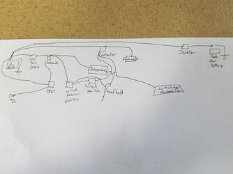
So this is my plan....look right? (sorry for my chicken scratches lol)

Ragnar406
The Great Bald One
Lifetime Member
Supporting Member
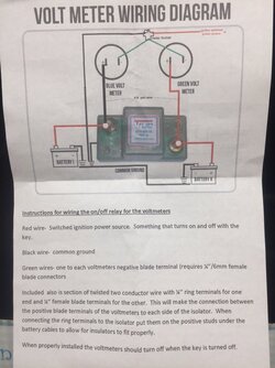
Any one know what relay they are using between the negative sides on the volt meters? I had two voltmeters already so I ordered the True kit without the meters - now I am not sure how to hook up where they will not come-on until the key is on.
Ragnar406
The Great Bald One
Lifetime Member
Supporting Member
Never mind on my question above - I went back and found the answer in this thread (Duh look there first) - not that I have gotten into my wiring I am approaching questions that I glossed over in my planning.... great threadI have one voltmeter connected to the Honda key-on power. I spliced into the wire that feeds to factory 12v accessory connection.
My second battery has an 80 amp solenoid that provides power to the Bussman. There is a switch on the dash to activate that solenoid. When I throw the switch, the solenoid is engaged and the Bussman and all my accessories become active. So my second voltmeter just comes off one of the Bussman fused lines. Only on when I activate the master switch (ie solenoid).
I'm not sure what switches you have but one of the posts needs 12v to activate the relay. I used one of the fused lines to feed all my relay switches. Hope that helps...
Could a SPDT work just the same or are you bringing the neg and Pos of each source threw the sw?Yeah - thats it. I think.
I have a mater switch that controls everything. It triggers the solenoid which feeds the Bussman.
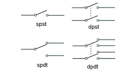
The DPDT switch can be:
- Off...or
- Key-on power triggers the solenoid... or
- Second battery triggers solenoid (via 5 amp fuse)
So I forgot - the middle position of the switch will also draw some current from the Honda battery when the key is on. Its not just the volt meter.
The only thing thats different is the winch that pulls directly from the second battery. The power to trigger the winch comes from the bussman - so also from the second battery. Im just kinda anal about isolating everything from factory.

advertisement
Tramguage1
Texan
Moderator
Lifetime Member
Supporting Member
Club Contributor
You only need to switch the positive side, the negitive/ground sides can all be bonded together.Could a SPDT work just the same or are you bringing the neg and Pos of each source threw the sw?
View attachment 38622
Sent from my SAMSUNG-SM-G935A using Tapatalk
Thank you that helps a lot.This is the switch i'm using but you could use another 3 position switch - actually I think a spdt 3 position switch would work.
And this is how i wired it.
View attachment 38630
Dragon21
In my defense, I was left unsupervised
Lifetime Member
Good thread. Been trying to figure out how to do my switches. DPDT is good idea. Guess I'll have to do a regular switch for my voltmeter/ 12 plugs to control that so they don't stay on all the time.
Thats why I ended up ordering a DPDT. That way, I dont accidentally leave it on....will stay in the keyed power position most of the time but can turn it on with key off if needed. The very first thing in my circuit after the 2nd battery is a 300A continuous duty golf cart solenoid, then EVERYTHING will be connected after that. The DPDT switch will activate that solenoid and everything (including volt gauges) will come to life. The only thing that will get key-on power is the backlight for the DPDT switch.
Dragon21
In my defense, I was left unsupervised
Lifetime Member
Hmm. Might have to look into that.Thats why I ended up ordering a DPDT. That way, I dont accidentally leave it on....will stay in the keyed power position most of the time but can turn it on with key off if needed. The very first thing in my circuit after the 2nd battery is a 300A continuous duty golf cart solenoid, then EVERYTHING will be connected after that. The DPDT switch will activate that solenoid and everything (including volt gauges) will come to life. The only thing that will get key-on power is the backlight for the DPDT switch.
Dragon21
In my defense, I was left unsupervised
Lifetime Member
Thats why I ended up ordering a DPDT. That way, I dont accidentally leave it on....will stay in the keyed power position most of the time but can turn it on with key off if needed. The very first thing in my circuit after the 2nd battery is a 300A continuous duty golf cart solenoid, then EVERYTHING will be connected after that. The DPDT switch will activate that solenoid and everything (including volt gauges) will come to life. The only thing that will get key-on power is the backlight for the DPDT switch.
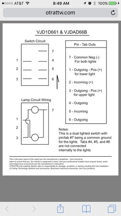
So the DPDT switch i got is a 7 Pin. Im guessing 1 is ground/ neutral. A +/1 for postion 1 (from ACC) and +/1 for position 2 (from 2nd Battery). and 2 outputs. Im assuming both outputs can be jumped together to run to the relay. for some reason i feel like im having a hard time with this switch wiring.
I haven't wired mine yet.....too busy but I'm planning on following what x4dice posted on post #74.So the DPDT switch i got is a 7 Pin. Im guessing 1 is ground/ neutral. A +/1 for postion 1 (from ACC) and +/1 for position 2 (from 2nd Battery). and 2 outputs. Im assuming both outputs can be jumped together to run to the relay. for some reason i feel like im having a hard time with this switch wiring.
Sent from my SAMSUNG-SM-G935A using Tapatalk
ohanacreek
My EcoBoost has I4WD
Moderator
Lifetime Member
So the DPDT switch i got is a 7 Pin. Im guessing 1 is ground/ neutral. A +/1 for postion 1 (from ACC) and +/1 for position 2 (from 2nd Battery). and 2 outputs. Im assuming both outputs can be jumped together to run to the relay. for some reason i feel like im having a hard time with this switch wiring.
That's a SPDT I think if it's lighted.
What's labeled as incoming is outgoing and outgoing incoming for this purpose.

If you've got this then just connect the light circuit to headlight circuit.
4 from battery /5 to Solenoid /6 from ignition
advertisement
Similar threads
- Replies
- 1
- Views
- 448
P
- Replies
- 16
- Views
- 1K
P
C
- Replies
- 1
- Views
- 362


