P1000 Help!! Wiring switch panel and voltmeters

Dragon21

Dragon21

In my defense, I was left unsupervised
Lifetime Member
Sep 23, 2013
1,309
2,920
113
Raleigh, NC
Ownership

  1. Do not currently own
That's a SPDT I think if it's lighted.

What's labeled as incoming is outgoing and outgoing incoming for this purpose.

View attachment 46225

If you've got this then just connect the light circuit to headlight circuit.

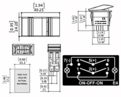
4 from battery /5 to Solenoid /6 from ignition

Amazon.com : Bandc Marine Boat Car 7 Pins 2 Light Blue Led On-off-on Rocker Switch Dpdt Waterproof 12v 24v : Sports & Outdoors

Thats the one i got. Looks the same as your diagram. Why 4,5,and 6 instead of 1,2,and 3? or does it not matter.

Thanks!!
 
ohanacreek

ohanacreek

My EcoBoost has I4WD
Moderator
Lifetime Member
Jul 25, 2013
11,346
32,050
113
Shelby County, Alabama
Ownership

  1. 1000-5
  • Like
Reactions: Dragon21
ghost

ghost

Well-Known Member
Lifetime Member
Dec 4, 2015
993
1,874
93
BC
Amazon.com : Bandc Marine Boat Car 7 Pins 2 Light Blue Led On-off-on Rocker Switch Dpdt Waterproof 12v 24v : Sports & Outdoors

Thats the one i got. Looks the same as your diagram. Why 4,5,and 6 instead of 1,2,and 3? or does it not matter.

Thanks!!
What ohanacreek said...
You can double check your understanding of switch wiring by connecting the circuit on your bench with fuses and an LED to simulate your load. Then you can see when the switch lights up and when power is applied to the load in each switch position. I did that with mine while doing this setup.

That switch diagram on your amazon link is confusing to me - I like the one ohanacreek posted. They represent the same type of switch.

I believe the switch was design to use 1,2 and 3 for the internal LEDs so its possible they are not rated for the same current. Probably are - but best to use the switch as intended.
 
  • Like
Reactions: Dragon21
Dragon21

Dragon21

In my defense, I was left unsupervised
Lifetime Member
Sep 23, 2013
1,309
2,920
113
Raleigh, NC
Ownership

  1. Do not currently own
Use 456 and you can jumper over to 1-4 and 3-6 to control the lights. But don't jumper 2-5 or you'll cause a short.in either on position.

Thanks! So it really doesnt matter if i use 2 or 5 correct, just as long as i dont jumper both? I appreciate the help!
 
  • Like
Reactions: ohanacreek
Dragon21

Dragon21

In my defense, I was left unsupervised
Lifetime Member
Sep 23, 2013
1,309
2,920
113
Raleigh, NC
Ownership

  1. Do not currently own
@Skyhawk85

I think there is another recent thread I replied to as well with the pins used. I can look when I get home
 
Bigtee

Bigtee

Well-Known Member
Lifetime Member
Supporting Member
Aug 20, 2017
556
1,213
93
Grayson, KY
Ownership

  1. 520

  2. 1000-5
I have one voltmeter connected to the Honda key-on power. I spliced into the wire that feeds to factory 12v accessory connection.

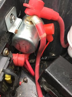
My second battery has an 80 amp solenoid that provides power to the Bussman. There is a switch on the dash to activate that solenoid. When I throw the switch, the solenoid is engaged and the Bussman and all my accessories become active. So my second voltmeter just comes off one of the Bussman fused lines. Only on when I activate the master switch (ie solenoid).

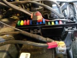
I'm not sure what switches you have but one of the posts needs 12v to activate the relay. I used one of the fused lines to feed all my relay switches. Hope that helps...


Ghost, do you have information on the solenoid you used?
 
Amre2me2

Amre2me2

Well-Known Member
Aug 11, 2016
381
1,423
93
Colorado
Ownership

  1. 1000-3
You only need one volt meter. Just run both battery leads into a switch that feeds the one meter and switch back and forth between batteries to view current voltage. You can see my switch below the dash.

Image
 
  • Like
Reactions: Tigermark
advertisement
Muleyhunter

Muleyhunter

Member
Lifetime Member
Apr 19, 2018
34
49
18
Lake Kiowa, TX
Ownership

  1. 1000-5
Yeah - thats it. I think.
I have a mater switch that controls everything. It triggers the solenoid which feeds the Bussman.
The DPDT switch can be:
- Off...or
- Key-on power triggers the solenoid... or
- Second battery triggers solenoid (via 5 amp fuse)

So I forgot - the middle position of the switch will also draw some current from the Honda battery when the key is on. Its not just the volt meter.

The only thing thats different is the winch that pulls directly from the second battery. The power to trigger the winch comes from the bussman - so also from the second battery. Im just kinda anal about isolating everything from factory.
@ghost your setup sounds exactly like what I am trying to achieve. I can think of several scenarios where I want to run some stuff without key or lights on.Let me preface my question by stating that my electrical knowledge on wiring accessories is less than basic. Other than wiring up some trailer lights and various other basic things, my experience is nil. So be easy on me if I ask a stupid question. i have spent days cramming myself with info from the various threads on this forum and pretty sure I have enough knowledge to order all the various parts I need. With one exception, this solenoid you are using to power your PDM. Can you supply a link for what are you using or tell me the specs I would need to order one. Also, have you produced any kind of overall wiring diagram for your setup?

Update: 5 seconds after I posted this I saw youve already posted a link in post #89 so disregard
 
  • Like
Reactions: ghost
Muleyhunter

Muleyhunter

Member
Lifetime Member
Apr 19, 2018
34
49
18
Lake Kiowa, TX
Ownership

  1. 1000-5
This is the switch i'm using but you could use another 3 position switch - actually I think a spdt 3 position switch would work.
And this is how i wired it.
View attachment 38630
Okay, I think I am finally following the wiring on this dpdt switch after numerous flips back and forth between your diagram and the otrattw wiring diagram. But let me make sure.
1) As I understand it, terminal 1 is not used.
2)The lower indicator light will come on as long as the key is on, no matter what position the switch is on
3) The upper indicater light will only come on if terminal 3 is getting power, i.e. only if the solenoid is getting a power signal which indirectly is telling you your PDM is being powered

This is all new to me and I have been cramming my head with all kinds of info from this forum. So if I have it wrong, please let me know. Just want to make sure I have it right before I start hooking things up
 
BWAF

BWAF

I get paid to pass gas
Lifetime Member
Jan 24, 2018
8,869
42,494
113
Carthage MO
Ownership

  1. 1000-5
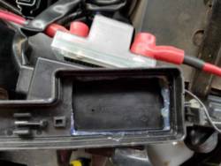
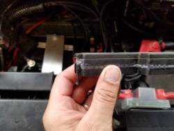
I'll come up with something even if I have to use the posi-tap but I really wanted this to work.. I guess I could cut a square notch in it, put in a height spacer in the hole and then jbweld over it.
Ordered another lid for mine cut center out of one epoxy the two together looks like they'll fit together like Legos $4 hope mine comes in this week

Sent from my SM-G930U using Tapatalk
 
  • Like
Reactions: Montecresto
ghost

ghost

Well-Known Member
Lifetime Member
Dec 4, 2015
993
1,874
93
BC
Okay, I think I am finally following the wiring on this dpdt switch after numerous flips back and forth between your diagram and the otrattw wiring diagram. But let me make sure.
1) As I understand it, terminal 1 is not used.
2)The lower indicator light will come on as long as the key is on, no matter what position the switch is on
3) The upper indicater light will only come on if terminal 3 is getting power, i.e. only if the solenoid is getting a power signal which indirectly is telling you your PDM is being powered

This is all new to me and I have been cramming my head with all kinds of info from this forum. So if I have it wrong, please let me know. Just want to make sure I have it right before I start hooking things up
Yup - that's how mine works.
If I'm not sure how some thing will work I'll hook it up with temporary leads and test it out. I'd rather troubleshoot it on the bench before installation.

Even after that, I accidentally had the solenoid powered by the primary battery and it was drained when I accidentally left the switch on. Easy to test - disconnect the main battery and make sure eneryrhing works the way you expect. If I did that test I would have seen that my custom circuit was not isolated from the primary system.
 
RedFred1

RedFred1

Well-Known Member
Aug 4, 2018
301
619
93
North Carolina
Ownership

  1. 1000-3
@Skyhawk85

I think there is another recent thread I replied to as well with the pins used. I can look when I get home


Most of these dpdt switches are similar... Two switches in one package with 123 is a switch with 2 being common & 456 are a switch with 5 being common. 7 and 8 is your switch led lights (if you have them). The switch shown below is in the off (center) position notice nothing connected to common on either switch. Pushing up connects 3-2 and 6-5, pressing rocker down connects 1-2 and 4-5.

81cE0fzlfEL SX679

Hope that helps...

FredD
 
Last edited:
  • Like
Reactions: BWAF
BWAF

BWAF

I get paid to pass gas
Lifetime Member
Jan 24, 2018
8,869
42,494
113
Carthage MO
Ownership

  1. 1000-5
Ordered another lid for mine cut center out of one epoxy the two together looks like they'll fit together like Legos $4 hope mine comes in this week

Sent from my SM-G930U using Tapatalk
Yep worked like I wantedF8097372330c9efb2f818b34a1953523D462f0fb9ed598c41a543dc43070f2d0E4a8a2d5ac5326a3a35dfd68f9e3836a

Sent from my SM-G930U using Tapatalk
 

About us

  • Our community has been around for many years and pride ourselves on offering unbiased, critical discussion among people of all different backgrounds. We are working every day to make sure our community is one of the best.

User Menu

Buy us a beer!

  • Lots of time and money has gone into making sure the community is running the best software, best designs, and all the other bells and whistles. Care to buy us a beer? We'd really appreciate it!

    Beer Fund!

    Club Membership!