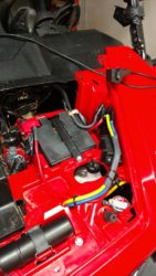
P1000 Pioneer 1000 Terra45 Winch Install.

Johnny_C

Johnny_C

Active Member
Nov 19, 2015
303
143
43
Western N. Carolina
Well, I finally got to work on my winch, aux battery, switch panel
etc, install today. I got the switch lighting wires built & tested.
I also was able to test my winch. I had the the winch motor on
the right side of the P1k, but reversed it a few days ago per the
discussion about the winch needing an underwind arrangement.
Well, in my testing it became apparent that I have backwards!
The motor & the electrical terminals should be on the right side.

Oh well, it makes for good practice taking things apart a bazillion
times, I suppose.

I double checked my wiring & according the instructions, that's
all good. The diagram on page 3 is either not detailed enough,
or it's just wrong. The diagram on page 5 is correct.


This has has been a fun project so far.

John
 
  • Like
Reactions: pct
Johnny_C

Johnny_C

Active Member
Nov 19, 2015
303
143
43
Western N. Carolina
It's actually 5 relayed & 5 fused outputs.

FYI

John

the cooper busman pdm that jackal and others have used on their builds has 5 fused relays and 10 fuses in one convenient package. it makes life simpler for adding multiple accessories because your relays and fuses are already to go in a plug and play module. a single heavy gage wire from your battery to the pdm powers all the relayed and fused accessories that you add to your vehicle (instead of having to wire them all up separately and potentially run individual power wires to each relay). it's not necessarily required for mounting the winch. It's just a convenient way to buy/install a new power center similar to your stock fuseblock and relay system.
as far as the cable angle, I believe all mounts end up with the same angle.
 
N

Ned

Active Member
May 12, 2015
241
183
43
West Kentucky
Ownership

  1. 1000-5
The angle at a roller fairlead causes a negligible increase in the overall stress in the wire rope cable. The primary stress seen by the winch cable, axial stress, dwarfs any stress added by the bend over the roller fairlead. The hawse type are not ideal, but they will eventually wear into a smooth transition.

Whoa....and the next entry on the effects of D&d ratio's on service life...thanks for the info....I had to look most of that up...and now that I have, it seems to my noobie simple mind that the angle over the hawse is in a way a replication of a line over a drum and applying the same ideas of the top of the line elongating more that the bottom, therefore decreasing service life, whereas without this angle forces would be all axial??? But what the heck do I know. If they are building them this way and everyone is using them this way (including Honda), I take your word that the angle over the hawse will be negligible in it's affect.
 
  • Like
Reactions: pct
PioneerPete

PioneerPete

Well-Known Member
Lifetime Member
Jan 3, 2016
1,496
3,516
113
Chattanooga, TN
Ownership

  1. 1000-5
It's actually 5 relayed & 5 fused outputs.

FYI

John
yes, thank you for clarifying that for me. 5 relayed outputs WITH fuses, and 5 plain fused outputs, for a total of 10 outputs.
 
PioneerPete

PioneerPete

Well-Known Member
Lifetime Member
Jan 3, 2016
1,496
3,516
113
Chattanooga, TN
Ownership

  1. 1000-5
Whoa....and the next entry on the effects of D&d ratio's on service life...thanks for the info....I had to look most of that up...and now that I have, it seems to my noobie simple mind that the angle over the hawse is in a way a replication of a line over a drum and applying the same ideas of the top of the line elongating more that the bottom, therefore decreasing service life, whereas without this angle forces would be all axial??? But what the heck do I know. If they are building them this way and everyone is using them this way (including Honda), I take your word that the angle over the hawse will be negligible in it's affect.
Well what I was trying to say was that the roller fairlead with the large lower drum is probably more ideal than the hawse style. The hawse style will eventually wear into a smooth rounded surface similar in shape to the drum on the roller style fairlead, but maybe not as large a diameter shape as the roller drum. So, considering the angle due to the low winch mount, my opinion is that the roller fairlead is better than the hawse for use with a wire rope. If I really wanted to run a hawse style fairlead, then I would make sure to use the synthetic rope. I would shy away from using the wire rope with the hawse fairlead due to the d/D concerns. I don't think the d/D matters as much for the synthetic rope.
 
Johnny_C

Johnny_C

Active Member
Nov 19, 2015
303
143
43
Western N. Carolina
I spaced my winch up higher with some
spacers & longer bolts. I also drilled new
holes in the bumper to move the hawse
down lower. 1/2 each, 1" less overall.

Ever little bit should help, I hope!

John
 
  • Like
Reactions: PioneerPete
T

TheBob

Member
Feb 15, 2016
58
57
18
North West Arkansas
My question is more related to the switch panel. It appears you drilled out the rivets holding the obligatory death warning placard below the transfer case selector switch, and removed it? Is there still a solid panel of plastics behind it? Did you have to cut holes in that as well? If so, where did you get the template to make the cuts? Just need more details on that switch panel if you have the info...

Thanks !
 
dale5740

dale5740

Well-Known Member
Lifetime Member
Supporting Member
Feb 4, 2016
886
416
63
mt airy md
that area is all wide open in there take your hood off and u can reach all the way up in there and feel around and see some of it
 
PioneerPete

PioneerPete

Well-Known Member
Lifetime Member
Jan 3, 2016
1,496
3,516
113
Chattanooga, TN
Ownership

  1. 1000-5
My question is more related to the switch panel. It appears you drilled out the rivets holding the obligatory death warning placard below the transfer case selector switch, and removed it? Is there still a solid panel of plastics behind it? Did you have to cut holes in that as well? If so, where did you get the template to make the cuts? Just need more details on that switch panel if you have the info...

Thanks !
I drilled out the rivets and removed the death sticker. it is solid plastic behind it. like dale said, you can see the other side of that area from under the hood, which makes it easier when routing all your wires. the size hole you cut depends on the layout of switches that you decide on. I used a cordless sawzall to cut mine out. I ended up cutting the plastic to within about half inch of the original rivet holes and then used those holes to mount my new switch plate. if you look at the garage thread, "the making of pete", you will see some pics of the switch layout that I used and the hole that I cut. glad to help if you have more questions.
 
  • Like
Reactions: TheBob and pct
T

TheBob

Member
Feb 15, 2016
58
57
18
North West Arkansas
I drilled out the rivets and removed the death sticker. it is solid plastic behind it. like dale said, you can see the other side of that area from under the hood, which makes it easier when routing all your wires. the size hole you cut depends on the layout of switches that you decide on. I used a cordless sawzall to cut mine out. I ended up cutting the plastic to within about half inch of the original rivet holes and then used those holes to mount my new switch plate. if you look at the garage thread, "the making of pete", you will see some pics of the switch layout that I used and the hole that I cut. glad to help if you have more questions.


Thanks! Good info. Making a list of the add on's I want to do, to get an idea of how many switches I will need, and where to put them. Heading to see Pete being made now....
 
  • Like
Reactions: pct and PioneerPete
PioneerPete

PioneerPete

Well-Known Member
Lifetime Member
Jan 3, 2016
1,496
3,516
113
Chattanooga, TN
Ownership

  1. 1000-5
Thanks! Good info. Making a list of the add on's I want to do, to get an idea of how many switches I will need, and where to put them. Heading to see Pete being made now....
I've made a few tweaks to the switch panel. Nothing major, just replaced the winch toggle with a 12v power switch to control the usb outlet and winch remote. also cleaned up the "bus bolt". I will add some more recent pics soon.
 
  • Like
Reactions: LaVell
T

TexHonda1000-5

New Member
May 27, 2016
3
1
3
Canyon Tx
Ownership

  1. 1000-5
HondaSXS,

Hello, I have been watching this forum every day since I buying my Pioneer 1000-5 in November. Very informative stuff, appreciate all the effort that goes into it. So I decided to install my Terra 45 and accessories as was described in this thread (HONDASXS with PDM) and have ran into some questions. I wired a Winch On/Off switch next to a Winch In/Out Switch, they both get power from the PDM on a 10amp circuit and in turn supply power to the in/out terminals on the winch solenoid. the main power supply and everything else appears to be routed the same as HondaSXS post in the beginning. Me and my buddy helping (the brains) figured the PDM would be enough to trigger the switching in the solenoid and since the main power comes from the battery. Its hard from the description to determine exactly how you got your power to the solenoid from your switch. Problem we are having is when you turn the winch power switch on and then hit the IN/Out switch the winch works like it should. as soon as you let go of the In/Out it faults the PDM and turns that circuit red, the others stay orange. Reset by turning power on and off and it works again until you let go of the IN/Out switch and then faults. Our solution was the PDM was not meant for this type of load and we ran the power from the IN/OUT switch thru a relay and have power coming from battery to relay, that way the PDM is only having to power the relay and get power to solenoid from relay/battery. Also the lead from battery to relay is fused. Sorry this is my first post ever on a forum and I don't have pictures. So any advice would be appreciated as I am not an experienced electrician by any means. How did you get power to the solenoid, and if you used the PDM did you have any issues? Note. we also tried on a 15amp circuit and got the same fault.
 
Hondasxs

Hondasxs

Club Founder
Staff member
Feb 13, 2013
18,037
63,542
113
Charlotte, NC
HondaSxS.com
Ownership

  1. 1000-5

  2. Talon R
Welcome @TexHonda1000-5,
I will help you out. We may need to explane a few things to each other to ensure we are talking about the same thing. I have also marked the topic to re-read to clarify. Sometimes its hard to put into words what I am trying to explain without confusing everyone.. haha.

Anyways.
Lets start at the winch solenoid (or contactor) with the 4 main terminals.
Two of these should go to the battery. In my picture, they are the Red and Black. Red runs through the circuit breaker then to the battery positive. The other 2, Yellow and Blue, run to the winch.
Do you have that set up like that?

Still talking about the contactor/solenoid here....
You have the 2 control wires (green and black). These wires run to the switch on the 12v OUT. One to the output of the IN switch and other to the output of the OUT switch.

Next you need positive from the PDM.
Choose one wire, anyone really, Think I chose the white wire.
Run it to the ON/OFF switch positive or "supply" terminal.
Then run the output of the OFF/ON wire to the winch IN/OUT Supply terminal.

Now assuming your PDM is running correctly it should all work.

Hit me back with questions.
Thanks.
 
  • Like
Reactions: Ragnar406
Hondasxs

Hondasxs

Club Founder
Staff member
Feb 13, 2013
18,037
63,542
113
Charlotte, NC
HondaSxS.com
Ownership

  1. 1000-5

  2. Talon R
You also have the remote wire. This has 3 wires. Red, Green, Black.
Red wire needs to also connect to the ON/OFF output terminal. You can crimp them together if you like. Green and Black connect to the solenoid splitter.

Need any more pics? Let me know shortly. I will be away Sat and Sun.
Thanks.
 
T

TexHonda1000-5

New Member
May 27, 2016
3
1
3
Canyon Tx
Ownership

  1. 1000-5
Thank you HondaSxs, yes I believe we are talking about the same thing. From your description it sounds like the way we wired the winch switches to the solenoid (contactor). We tryed to rule out as many options as we could, tried the 15 amp #5 wire from pdm just incase it wasnt enough to trip contactor, tried switching our in/out leads from switch to winch contactor. Only way we could get fault to go away was to run the pdm power thru a relay to the switch, then to the contactor, this was after a couple hours troubleshooting. Figured let the relay supply battery power to the switch and carry the load to contactor cause maybe the pdm couldnt handle it. Weird thing to us the fault didnt happen when you pushed in or out and winch was working, it only faulted when we let go of the switch and power was taken off contactor. Seems like if it was gonna fault the pdm it would happen with a load on it. Thanks for the help and any more suggestions are welcome, maybe i got a bad pdm off amazon or something. Im gonna go over everything per your description soon as I get a chance. Might be a couple days for me too, sounds like wife has made the fam some plans all weekend, lol guess shes not as concerned about getting the Honda put back together.

Sent from my SM-G935P using Tapatalk
 
Hondasxs

Hondasxs

Club Founder
Staff member
Feb 13, 2013
18,037
63,542
113
Charlotte, NC
HondaSxS.com
Ownership

  1. 1000-5

  2. Talon R
And...
The PDM is hooked up correctly? Including the positive, negative, and trigger wire?
 
Last edited:
T

TexHonda1000-5

New Member
May 27, 2016
3
1
3
Canyon Tx
Ownership

  1. 1000-5
Thanks Hondasxs, appreciate the informative post and help!Ive had it up and running for a couple weeks and all seems good, appreciate the assist!
Uploadfromtaptalk1466021265977


Sent from my SM-G935P using Tapatalk
 
  • Like
Reactions: Hondasxs
ToddACimer

ToddACimer

Pioneer 1005-2
Lifetime Member
Oct 7, 2016
3,559
14,599
113
Oshkosh, Wi
Ownership

  1. 1000-5
Thanks for the clear photos of your install. This thread was very helpful getting the wire routings nice and clean. I did change the location of the circuit breaker but overall this worked well

IMG 20161112 200357509
 
IdahoPioneer

IdahoPioneer

Well-Known Member
Oct 16, 2015
244
600
93
Emmett, Idaho
Ownership

  1. 500

  2. 1000-5
Hey guys, I've got to ask another question about the sharp angle of the winch cable. I am finishing up my install of this exact setup and noticed the angle. I'm thinking of ordering a roller fairlead to keep from tearing up the rope. Can anyone share their long term experience with this setup so I know if it's going to be a major issue?
 
ToddACimer

ToddACimer

Pioneer 1005-2
Lifetime Member
Oct 7, 2016
3,559
14,599
113
Oshkosh, Wi
Ownership

  1. 1000-5
I would not use a roller fairlead with a synthetic cable. The gap between the rolls when pulling at an angle can pinch the cable adding stress to the cable. Additionally the rollers can pick up dirt on their full diameter which can embed in the rope as it rolls.
 
  • Like
Reactions: ohanacreek

About us

  • Our community has been around for many years and pride ourselves on offering unbiased, critical discussion among people of all different backgrounds. We are working every day to make sure our community is one of the best.

User Menu

Buy us a beer!

  • Lots of time and money has gone into making sure the community is running the best software, best designs, and all the other bells and whistles. Care to buy us a beer? We'd really appreciate it!

    Beer Fund!

    Club Membership!