HondaSXS,
Hello, I have been watching this forum every day since I buying my Pioneer 1000-5 in November. Very informative stuff, appreciate all the effort that goes into it. So I decided to install my Terra 45 and accessories as was described in this thread (HONDASXS with PDM) and have ran into some questions. I wired a Winch On/Off switch next to a Winch In/Out Switch, they both get power from the PDM on a 10amp circuit and in turn supply power to the in/out terminals on the winch solenoid. the main power supply and everything else appears to be routed the same as HondaSXS post in the beginning. Me and my buddy helping (the brains) figured the PDM would be enough to trigger the switching in the solenoid and since the main power comes from the battery. Its hard from the description to determine exactly how you got your power to the solenoid from your switch. Problem we are having is when you turn the winch power switch on and then hit the IN/Out switch the winch works like it should. as soon as you let go of the In/Out it faults the PDM and turns that circuit red, the others stay orange. Reset by turning power on and off and it works again until you let go of the IN/Out switch and then faults. Our solution was the PDM was not meant for this type of load and we ran the power from the IN/OUT switch thru a relay and have power coming from battery to relay, that way the PDM is only having to power the relay and get power to solenoid from relay/battery. Also the lead from battery to relay is fused. Sorry this is my first post ever on a forum and I don't have pictures. So any advice would be appreciated as I am not an experienced electrician by any means. How did you get power to the solenoid, and if you used the PDM did you have any issues? Note. we also tried on a 15amp circuit and got the same fault.
--------------------------------------
I encountered the same problem as observed by
@TexHonda1000-5. I used an oscilloscope to trace down the problem and thought I would share my findings with others.
Issue
This scenario exists when using a PDM60 as the power source to the Up/Down switch that is connected to a winch contactor. The contactor is an electromagnetic switch that controls the electrical power to the winch. When releasing the switch from either the “In” or “Out” position, the PDM60 will frequently trip some of the circuits and will need to be reset. This problem can occur whether or not the winch is under load.
Cause
When pressing the “In or “Out” position on the switch, 12V will be applied to the solenoid coils found on the winch contactor, which will then activate the winch. Once the switch is release, there is residual energy stored in the solenoid coil which results in a high frequency/high voltage oscillation due to the inherent inductance and parasitic capacitance found in the contactor coils. This high frequency oscillation will dampen after a few hundred microseconds, however there is sufficient time to effectively capacitively couple across the In/Out switch which ultimately puts the PDM60 in a fault condition. In my case, several of the PDM60 outputs were is a fault state (red and orange LEDs). Keep in mind, this phenomenon happens nearly instantaneously after the switch is released and while the Up/Down switch contacts are still extremely close to each other.
Solution
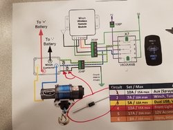
Fortunately, this problem is easy to fix. My contactor was shipped from the factory with a jumper from the solenoid ground pin to the negative voltage slug on the winch side of the contactor. If possible, disconnect this jumper and run a wire from the solenoid ground to a location as close as possible to the PDM60 ground. Next, place a voltage suppressor (Zener Diode) on both the Up solenoid pin and Down solenoid pin to the solenoid ground pin. Make sure the suppressor is close to the winch contactor. The voltage suppressor I used was 1N6276A. The suppressor will eliminate the high voltage/high frequency oscillations. The attached schematic shows how the voltage suppressor is wired to the contactor.


