All,
I picked up a number of useful tips on these threads prior to installing my Superwinch Terra 4500 on my P5. I wanted to combine all the best tips plus some of my own to create the ultimate winch installation guide.
The mounting plate I used was from KFI Products. It’s a wonderful fit and allows for the winch to be mounted top side. The Warn kit marketed by Honda uses an upside mount but I like this style much better as the finished product will sit as shown in PIC1. Found mine on Amazon for $50.
http://www.kfiproducts.com/index.php?_a=viewProd&productId=571
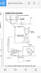
Moving on to wiring. Yes its true they will be switched. The shorter red and black cables will go from the solenoid to the winch itself. The longer blue and yellow cables will extend from the solenoid all the way back to the battery box.
But let’s start from the beginning. First there are many threads about the use of Honda’s accessory Harness when not using the Honda kit from Warn. I purchased it from my dealer just in case. For a measly $10 it proved itself invaluable and I’ll explain how in this section. It’s Honda part number 08Z08-HL5-A00. One end plugs into the 4P red connector under the hood. Once the harness is plugged in you have 4 open female cables (each of a different color) that receive power when ignition key is on. In the PIC2 I’m holding the harness. By the end of my installation I used 2 of the 4 open connections.
So basically the rocker switch needs power as does the optional remote socket if you choose to mount and use it. The Superwinch instructions tell you to splice into the ignition switch wires. Other threads on these forums have discussed splicing into the 12v accessory wire also. This is where the sub harness came in handy. Instead of splicing anything I bought two male connectors (shown in PIC3) for $1 and crimped on the wires to power the both the rocker switch and the remote socket, then plugged these male connectors into the sub-harness. No splicing needed.
Incidentally there has been much discussion on these forums as to the ideal location to mount the rocker switch and/or socket assembly. PIC4 is where I chose to mount them.
Moving on – the solenoid itself is mounted in the only location it can be and the one agreed by all in these forums. As you are facing the front its on the left hand side near the back – here Honda left a frame crossmember with openings designed for the solenoid installation. Please see PIC5 – the hardware from the superwinch kit will allow you to mount it here.
PIC6 shows how I routed the red and black wires from the solenoid down to the winch. That part was easy.
To run the blue and yellow cables back to the battery I did drop the skid plates. Some if these forums did the same some did not. I figured if it made it at all easier I would do the extra step. Once skid plates were off I initially dropped the blue and yellow wires down from the solenoid, behind the coolant overflow and right alongside a black electrical tube as shown in PIC7. Once that was done it was quite easy to route them along the frame to the back end.
Now here comes the tricky part. Many people have done many different things when it comes to hooking the yellow and blue wires to the battery. In addition, some people have utilized the provided circuit breaker from Superwinch, others have not. Here is what worked for me.
The blue wire (which goes to the negative post) was very easy. There is room for one wire to sneak in with the ones already in place. I simply routed my blue one into the box with the others. PIC8 and PIC9 show two different views of the blue wire – one with battery cover on and one with it off.
Now for the yellow wire. PIC9 and PIC10 show how I decided to route it. I ended up drilling a hole in the bottom of the battery box on the left hand side and came up through the hole.
Inside the battery box on the left hand side where my yellow wire came up is a plastic slot. I filed that down just a bit with a Dremel and was able to stand the circuit breaker up. The yellow wire attaches to the bottom of the circuit breaker and the short supplied red one attaches the other end of the breaker to the actual positive post as shown in PIC11.
Once everything was connected I zip tied the yellow and blue wires to the frame in spots and put back on the skid plates. Then I tidied up under the hood as best I could be wrapping excess wires for the rocker switch and socket assembly, etc..etc…
I truly hope this helps! Thanks to everyone whose ideas helped get me this far.
Kind Regards,
Jason
View attachment 6997 View attachment 6998 View attachment 6999 View attachment 7000 View attachment 7001 View attachment 7002 View attachment 7003 View attachment 7004 View attachment 7005 View attachment 7006 View attachment 7007


