P700 Wiper Wiring Diagram

ohanacreek

ohanacreek

My EcoBoost has I4WD
Moderator
Lifetime Member
Jul 25, 2013
11,346
32,043
113
Shelby County, Alabama
Ownership

  1. 1000-5
Who speaks electrical engineer?

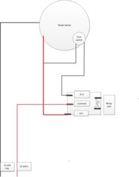
I need help deciphering this diagram for a wiper motor, I cannot disassemble the assembly without the high likelihood of destroying it.


UPDATE

This is for everyone who wants the Wiper but not use the Honda Aux Panel.

28372eca505fc83827bb1592efbfa2a5

Spifyd,
The non-North Americans switch the Negative(glad I had fuses) I wouldn't have figured it out without you pointing me the right direction. Many thanks.
 

Attachments

  • Wiper Diagram.tiff
    37.6 KB · Views: 1,524
  • Like
Reactions: Lady01 and AKRider
bigc

bigc

Moderator
Moderator
Lifetime Member
Supporting Member
Sep 16, 2013
421
93
28
Re: Wiper Wiring Diagram Help needed

thats an easy diagram what do you need to know come on mr.JCI lol
 
  • Like
Reactions: Lady01
ohanacreek

ohanacreek

My EcoBoost has I4WD
Moderator
Lifetime Member
Jul 25, 2013
11,346
32,043
113
Shelby County, Alabama
Ownership

  1. 1000-5
Wiper Wiring Diagram Help needed

31b and 53a, change based on where the wiper is in its cycle. I'm trying to figure out how to wire a no/nc relay to get the wiper back to its resting/starting position. So that when the circuit across 31-53 is broken on neg side, as it appears to be from the diagram, the relay will work to get it back to the resting position.

I haven't seen those symbols in 10 years. It's also wired backwards, being switched negative, from how I normally wire. Gotten old enough to start forgetting things apparently.
 
  • Like
Reactions: Lady01
Realtreegrizzly

Realtreegrizzly

Member
Jan 20, 2014
38
16
8
Re: Wiper Wiring Diagram Help needed

Can you remove the wiper arm and let the motor park then put the arm on in the position you want it
 
  • Like
Reactions: Lady01
ohanacreek

ohanacreek

My EcoBoost has I4WD
Moderator
Lifetime Member
Jul 25, 2013
11,346
32,043
113
Shelby County, Alabama
Ownership

  1. 1000-5
Re: Wiper Wiring Diagram Help needed

No because it's the park switch I'm trying to wire up. Right now it runs and stops wherever I cut power to it.
 
  • Like
Reactions: Lady01
spifyd

spifyd

Active Member
Lifetime Member
Jan 2, 2014
420
178
43
newhampshire
Re: Wiper Wiring Diagram Help needed

There are 4 wires on the wiper motor. The power goes through the wires you are running it on now. when you want it to park you run the power through the other two wires to the power wire you are using now.i cant remenber the colors.
but the other two wires go through a switch that is open in the wiper is parked.
 
  • Like
Reactions: Lady01
spifyd

spifyd

Active Member
Lifetime Member
Jan 2, 2014
420
178
43
newhampshire
Re: Wiper Wiring Diagram Help needed

is this a Honda wiper.
I made a simple diagram
 

Attachments

  • wiper motor.pdf
    92.1 KB · Views: 1,153
  • Like
Reactions: Lady01
spifyd

spifyd

Active Member
Lifetime Member
Jan 2, 2014
420
178
43
newhampshire
Re: Wiper Wiring Diagram Help needed

how about a jpg
 

Attachments

  • wiper motor.jpg
    wiper motor.jpg
    40.7 KB · Views: 3,805
  • Like
Reactions: Lady01
ohanacreek

ohanacreek

My EcoBoost has I4WD
Moderator
Lifetime Member
Jul 25, 2013
11,346
32,043
113
Shelby County, Alabama
Ownership

  1. 1000-5
Wiper Wiring Diagram Help needed

Yeah Honda wiper... I'll try that Tomo with a bunch of fuses all over the place, just in case it shorts that way I don't burn it up....that PDF actually makes perfect sense.

But their diagram does not.
 
  • Like
Reactions: Lady01
ohanacreek

ohanacreek

My EcoBoost has I4WD
Moderator
Lifetime Member
Jul 25, 2013
11,346
32,043
113
Shelby County, Alabama
Ownership

  1. 1000-5
Re: Wiper Wiring Diagram Help needed

This is for everyone who wants the Wiper but not the Honda Aux Panel.

D3d7aefbeb80b24c4d092963162e0a17

Spifyd,
The non-North Americans switch the Negative(glad I had fuses) I wouldn't have figured it out without you pointing me the right direction. Many thanks.
 
Last edited:
  • Like
Reactions: Lady01
spifyd

spifyd

Active Member
Lifetime Member
Jan 2, 2014
420
178
43
newhampshire
I didn't bother with a relay just a 15 amp switch. I thought I used switched pos. then I went back and looked at my diagram I made for my bike . ops! glade you got it sorted out.
 
  • Like
Reactions: Lady01
ohanacreek

ohanacreek

My EcoBoost has I4WD
Moderator
Lifetime Member
Jul 25, 2013
11,346
32,043
113
Shelby County, Alabama
Ownership

  1. 1000-5
Yeah a switch would work great if I'd planned for it being a different style but I had 3 extra relay spots in my fuse block and it was WAY easier to get to and already wired for the most part. Also it was switched negative so it was easier to use a relay.
 
  • Like
Reactions: Lady01
spifyd

spifyd

Active Member
Lifetime Member
Jan 2, 2014
420
178
43
newhampshire
I found this this morning. its the diagram I made for my bike. it looks like I am a + switching guy, until the wipers.
 

Attachments

  • PIONEER_ELETRICAL_(1).jpg
    PIONEER_ELETRICAL_(1).jpg
    156.9 KB · Views: 8,104
  • Like
Reactions: Lady01
H

hobbes

New Member
May 4, 2015
16
12
3
Since I am getting ready to modify mine from Hondas OEM setup to something more multifunction. I have read this with a lot and notice that you guys set it up via switched neutral. From metering mine out I see something different and was hoping for some input. This is what I noted.

Switch on position
Red and green wire are opened from each other
Red wire receives 12v from the switches fed external source and goes out to the motor
Yellow wires loses 12v
Black wire is direct to the motor for negative

When running the yellow and green are connect till you read the park position based on continuity reading on my meter
When running and it reaches the park position the green and black have continuity for a brief moment and you lose continuity between the yellow and green wire

Switch off position
Red and green wire are closed together (until the internal motor switch is released after it hits the lull in the rotating part of the switch)
Red wire loses 12v from the external source at the switch
Yellow wire receives 12v from the switches fed external source and goes out to the motor
Black wire is direct to the motor for negative

This would allow one more complete rotation as the switch drops off that is inside the motor.

From what I can tell from a car wiper motor that has a park function typically the yellow wire always has power. For what ever reason Honda is using some sort of relay method through the switch to protect the motor to some degree.

I checked with my meter at the plug at the wiper motor itself when the switch is off and between just the black and the yellow there is 12v.

Possibly I may have missed some wire trick they did at the factory add on box (wish I did not have now) that I am not aware of to see that it is switched neutral.

Any thoughts or comments? I have about a week before I will be able to make up all my items to update the wiring.

Thanks
 
  • Like
Reactions: Lady01
ohanacreek

ohanacreek

My EcoBoost has I4WD
Moderator
Lifetime Member
Jul 25, 2013
11,346
32,043
113
Shelby County, Alabama
Ownership

  1. 1000-5
It was trial and error with fuses and multimeter, I was thinking in switched positive.

Someone else pointed out it was switched negative and gave me a basic understanding, still took me trial and error to figure out how to make it work.
 
  • Like
Reactions: Lady01
H

hobbes

New Member
May 4, 2015
16
12
3
thanks for the input. I was trying to find a dpdt relay that was sealed to some degree to do all the switching i needed. not so easy to find. I am going to use two relays to do this to maintain the separation of the red and yellow wires from having power at the same time. hate to use two but at this time that is what I will try to attempt. once I do it, i will post what i did, well if it works. if it fails, well i will try and catch the smoke.
 
  • Like
Reactions: Lady01
ohanacreek

ohanacreek

My EcoBoost has I4WD
Moderator
Lifetime Member
Jul 25, 2013
11,346
32,043
113
Shelby County, Alabama
Ownership

  1. 1000-5
I run mine a lot. No issues using the relay set up I have. Weather pack version is fairly easy to find.
 
  • Like
Reactions: Lady01
H

hobbes

New Member
May 4, 2015
16
12
3
weather pack for dpdt i need help finding for a 12vdc system that is compact enough. any help on this from everyone would be greatly appreciated.
 
  • Like
Reactions: Lady01
ohanacreek

ohanacreek

My EcoBoost has I4WD
Moderator
Lifetime Member
Jul 25, 2013
11,346
32,043
113
Shelby County, Alabama
Ownership

  1. 1000-5
weather pack for dpdt i need help finding for a 12vdc system that is compact enough. any help on this from everyone would be greatly appreciated.


DPDT is hard to find, I don't understand why you need it though. The SPDT works a DPDT will be wired in such a way that it would be basically a SPDT relay anyway. Most relays are watertight and being 12v if you diletric grease the connection it'll never arc.
 
  • Like
Reactions: Lady01

About us

  • Our community has been around for many years and pride ourselves on offering unbiased, critical discussion among people of all different backgrounds. We are working every day to make sure our community is one of the best.

User Menu

Buy us a beer!

  • Lots of time and money has gone into making sure the community is running the best software, best designs, and all the other bells and whistles. Care to buy us a beer? We'd really appreciate it!

    Beer Fund!

    Club Membership!