P1000 Yet Another Pioneer 1000 Dual Battery Install - video

aleaddict

aleaddict

Well-Known Member
Lifetime Member
Jan 17, 2021
128
739
93
Eagle, ID
Ownership

  1. 1000-5
SO, lets talk about switches and relays again...

@RobSparre in your *v301.pdf schematic you use a DPDT switch to toggle between key-on and always-on power source, with "off" being the middle position. I couldn't think of one scenario where I would not want power to all my accessories. This brought be back to relays, specifically the SPDT relay.

The SPDT has a common terminal, a normally closed (NC) terminal, and normally open (NO) terminal. The key-on power would be wired to the NC leg and the always-on to the NO side. A simple on/off switch would energize the coil, breaking contact with the NC (key-on) terminal and switching to the NO (always-on) terminal, thus eliminating the "all off" position using a regular DPDT switch.

Does anyone see a problem with using the SPDT relay as opposed to a DPDT switch to control the accessory power source? I'm beginning to layout my wiring and this was the only piece to the schematic that had me puzzled.
 
ACfixer

ACfixer

Global Warming Enthusiast
Lifetime Member
Jan 22, 2021
218
840
93
N/E Tennessee
Ownership

  1. 1000-5
^^^^ Without thinking it all through there aleaddict, what I kept running into without using unidirectional diodes etc, is backfeeding to the accessory circuit when I wanted to use my ancillary accessories but not power up the machine. The issue wasn't powering up my added stuff so much as it was keeping the buggy dash lights from coming on.

My solution was a master switch for everything I added other than turn indicators and horn which power up with my key. My master switch merely powers up my stinger relay and I get that power directly from my AUX battery.
 
RobSparre

RobSparre

Well-Known Member
Lifetime Member
Supporting Member
Oct 6, 2020
139
452
63
West Chester, PA
Ownership

  1. 1000-5
SO, lets talk about switches and relays again...

@RobSparre in your *v301.pdf schematic you use a DPDT switch to toggle between key-on and always-on power source, with "off" being the middle position. I couldn't think of one scenario where I would not want power to all my accessories. This brought be back to relays, specifically the SPDT relay.

The SPDT has a common terminal, a normally closed (NC) terminal, and normally open (NO) terminal. The key-on power would be wired to the NC leg and the always-on to the NO side. A simple on/off switch would energize the coil, breaking contact with the NC (key-on) terminal and switching to the NO (always-on) terminal, thus eliminating the "all off" position using a regular DPDT switch.

Does anyone see a problem with using the SPDT relay as opposed to a DPDT switch to control the accessory power source? I'm beginning to layout my wiring and this was the only piece to the schematic that had me puzzled.
As @ACfixer mentioned - the main concern and reason I used the DPDT switch in the example is due to the potential for leaking current for accessories that are "sort of on" and lightly draining battery without intentionally being on. I'm not smart enough to know exactly how or why a specific configuration "should work", like a SPDT switch instead, but I like to err on the side of being certain that everything is isolated to avoid any leaking current draw. I want a "definitely everything is off and isolated" position on the switch. So the SPDT should work - but I personally prefer the "definitely all off" position.
 
aleaddict

aleaddict

Well-Known Member
Lifetime Member
Jan 17, 2021
128
739
93
Eagle, ID
Ownership

  1. 1000-5
Copy all that @RobSparre and thanks for your video and thoughtful discussion 🤟:cool:👍

I've been trying to drill down on the problem of back feeding and from everything I've read a simple in/out diode on the key-on side may be the solution.

SPDT relay would be controlled by a rocker switch. Diode would go between key-on power source and SPDT relay (no need to protect against back feeding to Aux battery... I think lol). With rocker in OFF position, NC leg would carry current through key-on power source, which is the default position. Conversely, with rocker in ON position, NO condition directly energizes Stinger/solenoid from Aux battery AND back feeding main battery (dash lights, etc) would be protected by diode.

I have no clue if this will work but I'm ordering the Roadmaster 690 Single park light diode tonight and will report back with results, good or bad. I decided the relay with internal diode cited earlier would not work because it would be tied into the always-on side rather than the key-on side, where it belongs. Still trying to sort all this out...
 
ACfixer

ACfixer

Global Warming Enthusiast
Lifetime Member
Jan 22, 2021
218
840
93
N/E Tennessee
Ownership

  1. 1000-5
As @ACfixer mentioned - the main concern and reason I used the DPDT switch in the example is due to the potential for leaking current for accessories that are "sort of on" and lightly draining battery without intentionally being on. I'm not smart enough to know exactly how or why a specific configuration "should work", like a SPDT switch instead, but I like to err on the side of being certain that everything is isolated to avoid any leaking current draw. I want a "definitely everything is off and isolated" position on the switch. So the SPDT should work - but I personally prefer the "definitely all off" position.

I can't really add anything to that except that the "sort of on" thing is bush league at best. Whether you take a blue collar approach like I did with a master switch, or a white collar approach with diodes and such, it has to be addressed.

I can see you're a hunter aleaddict, no need for me to explain to you what could happen. If we walk from camp, we are always close enough to walk back right? If we take the buggy, we can get dangerously deep into the wilderness and stupid failures could be downright life threatening under adverse conditions and the last thing we need are weird electronic quirks 30 miles from camp with a storm blowing in. So for me it was a hard pass on anything more complicated than DC electricity 101.
 
S

sebowen

Member
Jun 18, 2021
15
54
13
Spring, TX
Ownership

  1. 1000-5
I am little confused on the DPDT switch wiring. Care to break that down for me and which switch you purchased? Please.
The switches I see for diagrams show the power going to "both" sides of switch. Same power? I don't see how it separates the power going into the Stinger for option of key on power vs all power if switch is on "other" side?

Can you show how you wired the DPDT switch?

Dpdt switch diagram
Dpdt switch
 
bumperm

bumperm

Well-Known Member
May 7, 2021
1,908
6,791
113
Gardnerville, NV
Ownership

  1. 1000-5
I am little confused on the DPDT switch wiring. Care to break that down for me and which switch you purchased? Please.
The switches I see for diagrams show the power going to "both" sides of switch. Same power? I don't see how it separates the power going into the Stinger for option of key on power vs all power if switch is on "other" side?

Can you show how you wired the DPDT switch?

View attachment 290648View attachment 290649
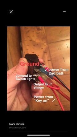
Right. Doesn't make a lot of sense as the switch shown in the diagram above is wired to behave as a SPDT (single pole double throw) switch. There is no need to switch ground, so upper wire labeled ground must be for switch illumination?
 
Hillbillytnt

Hillbillytnt

Well-Known Member
May 2, 2020
552
2,030
93
Ky
Ownership

  1. 1000-3
I am little confused on the DPDT switch wiring. Care to break that down for me and which switch you purchased? Please.
The switches I see for diagrams show the power going to "both" sides of switch. Same power? I don't see how it separates the power going into the Stinger for option of key on power vs all power if switch is on "other" side?

Can you show how you wired the DPDT switch?

View attachment 290648View attachment 290649
See if this helps. I’m not sure about your ? But it sounds like your trying to wire a master switch to control the stinger. This is a seven pin maintained on off on.

0376AB33 9154 4844 9A63 E3B2B9E7EC75
 
  • Like
Reactions: sebowen
advertisement
RobSparre

RobSparre

Well-Known Member
Lifetime Member
Supporting Member
Oct 6, 2020
139
452
63
West Chester, PA
Ownership

  1. 1000-5
I am little confused on the DPDT switch wiring. Care to break that down for me and which switch you purchased? Please.
The switches I see for diagrams show the power going to "both" sides of switch. Same power? I don't see how it separates the power going into the Stinger for option of key on power vs all power if switch is on "other" side?

Can you show how you wired the DPDT switch?

View attachment 290648View attachment 290649
The switch I am showing has 2 power input connections, both on the left side. The top left says "key-on accessory power". That means it will come from either a key-on harness or accessory fuse #5 from the main fuse box. It will not have power unless the stinger is energized and there is power to the aux fuse box. This is the way I wired mine and demonstrated in the video.

The other power input is from the positive bus, which is always hot, regardless of whether the key is on or not. .

The two output connections on the right side correspond with the appropriate input power. The top right of the switch diagram is for the Key-On position and currently shows ON and connected to the accessory bus. Conversely, in that position, the "always-on power" position is OFF.

The second output connection on the bottom right is for "always-on" (meaning it does not need the key to be on) and is currently shown as OFF in the example. When the switch is thrown, the upper right connection will move to OFF, and the bottom right connection will move to ON, and the accessory bus will be energized, even though the stinger is off.

Hopefully that helps. LMK if still confused.

I have no idea how the example switch you have is wired internally.
 
  • Like
Reactions: Lady01 and sebowen
S

sebowen

Member
Jun 18, 2021
15
54
13
Spring, TX
Ownership

  1. 1000-5
Awesome! I believe I understand it now. THANK YOU for your help!!

So it's basically reversing the input/output of the switch. So what would normally be the output power to 2 different devices, is now actually the input of 2 different power in and 1 single power out to engage the Stinger relay.

I don't have any switches yet. Just ordered the True isolator, extra battery, radio/speakers, fuse block, winch, blinker kit that I want to power all up via the 2nd battery.


New wiring
 
  • Like
Reactions: Lady01
Hondasxs

Hondasxs

Club Founder
Staff member
Lifetime Member
Supporting Member
Feb 13, 2013
18,511
67,231
113
Charlotte, NC
HondaSxS.com
Ownership

  1. 1000-5

  2. Talon R
Awesome! I believe I understand it now. THANK YOU for your help!!

So it's basically reversing the input/output of the switch. So what would normally be the output power to 2 different devices, is now actually the input of 2 different power in and 1 single power out to engage the Stinger relay.

I don't have any switches yet. Just ordered the True isolator, extra battery, radio/speakers, fuse block, winch, blinker kit that I want to power all up via the 2nd battery.


View attachment 290826
Yes, for that switch your diagram should be correct.
 
  • Like
Reactions: Lady01
RobSparre

RobSparre

Well-Known Member
Lifetime Member
Supporting Member
Oct 6, 2020
139
452
63
West Chester, PA
Ownership

  1. 1000-5
Awesome! I believe I understand it now. THANK YOU for your help!!

So it's basically reversing the input/output of the switch. So what would normally be the output power to 2 different devices, is now actually the input of 2 different power in and 1 single power out to engage the Stinger relay.

I don't have any switches yet. Just ordered the True isolator, extra battery, radio/speakers, fuse block, winch, blinker kit that I want to power all up via the 2nd battery.


View attachment 290826
Yes - very good summary - you’ve got it! Let us know how it turns out.
 
  • Like
Reactions: Lady01
S

sebowen

Member
Jun 18, 2021
15
54
13
Spring, TX
Ownership

  1. 1000-5
Just wanted to say thanks for the help in this thread (and forum) Everybody has been helpful! The dual switch (key/constant) for power idea is great and wouldn't have thought of that on my own!

Finished up installing extra battery, isolator, stinger relay, fuse block, winch, dash plate and switches (made my own from left over plastic and 3m carbon fiber sticker), radio, speaker pods, blinker kit, and whatever else I can't remember. Been a solid week of working on it in the evenings after work. Took it out for a spin today and enjoyed it down at the creek with the whole family!

I'm sure it could be a cleaner install, but I did it all myself. Maybe I'll clean it up more later, or maybe I'll just go enjoy it!

Dash radio
Under hood
 
RobSparre

RobSparre

Well-Known Member
Lifetime Member
Supporting Member
Oct 6, 2020
139
452
63
West Chester, PA
Ownership

  1. 1000-5
Just wanted to say thanks for the help in this thread (and forum) Everybody has been helpful! The dual switch (key/constant) for power idea is great and wouldn't have thought of that on my own!

Finished up installing extra battery, isolator, stinger relay, fuse block, winch, dash plate and switches (made my own from left over plastic and 3m carbon fiber sticker), radio, speaker pods, blinker kit, and whatever else I can't remember. Been a solid week of working on it in the evenings after work. Took it out for a spin today and enjoyed it down at the creek with the whole family!

I'm sure it could be a cleaner install, but I did it all myself. Maybe I'll clean it up more later, or maybe I'll just go enjoy it!

View attachment 292276View attachment 292277
Wow that looks fantastic - great job!! Very creative with component locations and very clean. Feels good to complete a job like that doesn’t it?
 
R

riverjetter

Member
May 10, 2021
25
49
13
Montana
Ownership

  1. 1000-5
Great video. Found it quite informative and was helpful in figuring out the necessary components to perform this task as well as placement of the components. I do have a couple questions however. Does the dual volt meter that comes with the True kit fit the switch plate hole or did you have to modify the switch plate to make it fit? Have you found a need for more switches than the original plate you installed which I believe was 5 switches with two different power adapters and the volt meter? Are you still adding accessories to the fuse box you purchased or is the six fuse enough? I'm in the process of ordering everything for a second battery install in my machine and was just wondering what you would do different now, from what you originally did. Thanks in advance.
 
RobSparre

RobSparre

Well-Known Member
Lifetime Member
Supporting Member
Oct 6, 2020
139
452
63
West Chester, PA
Ownership

  1. 1000-5
Great video. Found it quite informative and was helpful in figuring out the necessary components to perform this task as well as placement of the components. I do have a couple questions however. Does the dual volt meter that comes with the True kit fit the switch plate hole or did you have to modify the switch plate to make it fit? Have you found a need for more switches than the original plate you installed which I believe was 5 switches with two different power adapters and the volt meter? Are you still adding accessories to the fuse box you purchased or is the six fuse enough? I'm in the process of ordering everything for a second battery install in my machine and was just wondering what you would do different now, from what you originally did. Thanks in advance.
Thanks for the feedback and enjoy your project - it is very satisfying to the soul to do this! Very smart to ask if any changes in thinking since the video.

I said in the video I did not need the 12 position fuse box. Hahahahaha. I am currently up to 8 fuses and likely to use several more so the original fuse box purchase is needed with my endless additions.

fuses are voltmeter, usb charger, dc outlet, light bar, rear lights, dome lights, footwell lights, winch. Planning to add heater (video coming this fall - and I did videos on the winch, 10 suggested accessories, trailer, soft doors, and I have two others in the works - gps and cargo buckles)

dual voltmeter fits fine - no need to drill out further.

I am currently using 4 of the 5 switches. Winch, front LED light bar, dual rear lights, dome lights with dimmer. 1 switch left unused.

I am still not planning to add a stereo - although many people do. I am powering my gps from one of the USB ports. I am currently off-roading at Famous Reading Outdoors in PA, and the GPS was critical.

So far I am very happy with how things turned out and am using everything. I would probably try to make it a little cleaner wiring - wise - but I just didn’t have the patience to be more perfectionist about it.
 
  • Like
Reactions: TripleB
R

riverjetter

Member
May 10, 2021
25
49
13
Montana
Ownership

  1. 1000-5
Thank you so much. Your input it is greatly appreciated. I don't intend on putting a lot of useless "bling" on my machine just the items that are critical to hitting the hills here in our area. Just so you know we only have three seasons here in Montana, Summer, Winter, and Hunting. We also have a lot of snowfall. The area where I will mostly be using my machine has a ground snow load of 200 inches or better. Don't want to be stranded in that stuff for very long and the second battery is mainly for that situation. This was why I asked the question that I did. Survival mode, not show off mode. Thanks again and God Bless America, we need all the help we can get.
 
S

sebowen

Member
Jun 18, 2021
15
54
13
Spring, TX
Ownership

  1. 1000-5
Ok. I'm back with another question for you gurus.

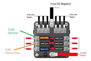
I used a 6 way fuse block with LED indicator that turns on via a switch to the stinger. So I got a little OCD and was using the fancy little stickers to label the fuse block circuits. (winch, radio, turn signal kit, etc). I was doing this by a process of elimination, meaning all the wires were zip tied and loomed up and a little hard to trace. So I pulled fuse, and see what didn't work. This worked until I got to the radio. Typical radio, 1 yellow wired to battery for clock memory, red to switched power when you want it to come on. So with the fuse pulled, radio still was on? WTH?

So I tested fuse block with circuit tester. 12.8 volts with power on and fuse in, 9.8 with fuse removed.

After a simple Google search, I found that this is normal, but doesn't let much amperage through. However, it is enough amperage to still turn on the radio (I guess because it pulls main power from yellow wire). But not blinkers, winch, or anything else so far. If I remove fuse for those items, which have a bigger amperage draw, they do not work. (as expected)

Anybody else have this happen? Any idea on how to fully "break" circuit as if the use was blown? Concerns me that if the fuse ever did actually blow! Then perhaps my radio might have permanent damage issues if ran for a period of time on less voltage.

98 volts 98 volts note
 
  • Like
Reactions: Lady01
advertisement

About us

  • Our community has been around for many years and pride ourselves on offering unbiased, critical discussion among people of all different backgrounds. We are working every day to make sure our community is one of the best.

User Menu

Buy us a beer!

  • Lots of time and money has gone into making sure the community is running the best software, best designs, and all the other bells and whistles. Care to buy us a beer? We'd really appreciate it!

    Beer Fund!

    Club Membership!