20160122_094255.jpg

P1000 Jackal's P1000-5

JACKAL

JACKAL

Ancient Honda fanboi
Moderator
Lifetime Member
Supporting Member
Club Contributor
Jun 11, 2015
40,212
275,470
113
Pioneer, TN
Ownership

  1. 1000-5

  2. Talon X4
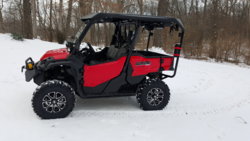
Had a blast today on maiden voyage. P1K5D performed beyond my expectations. Nasty weather but still logged 40 miles even with a 2 yr old.

Fb78e50439708c5dca1adf658750f72022f80e49eb7a1ee169a55f66caa6fe1a902a206a1c0ef23723f220cba8228c29
 
joeymt33

joeymt33

i4WD=imitated 4WD
Moderator
Lifetime Member
Supporting Member
Club Contributor
Mar 17, 2015
11,096
39,129
113
Guntersville, AL
Ownership

  1. 1000-3

  2. 1000-5
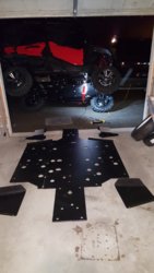
Can you share some details about the A-arm skids? I'm looking to buy some and I'd like to see some better pics than what they offer on the website.

Also, what do you think about them?
 
JACKAL

JACKAL

Ancient Honda fanboi
Moderator
Lifetime Member
Supporting Member
Club Contributor
Jun 11, 2015
40,212
275,470
113
Pioneer, TN
Ownership

  1. 1000-5

  2. Talon X4
Can you share some details about the A-arm skids? I'm looking to buy some and I'd like to see some better pics than what they offer on the website.

Also, what do you think about them?
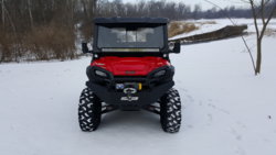
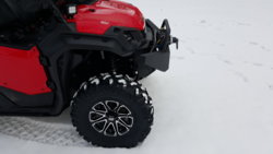
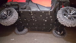
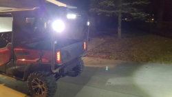
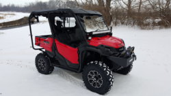
I like them fine they are very well designed and attached easily and sturdy. I bounced them off 40 miles of rocky trails without issue yesterday. The material seems harder or more rigid than other UHMW skids I have seen and handled the main skid is the same way too. I don't have any detailed pics yet but here is a frontal view.
 
JACKAL

JACKAL

Ancient Honda fanboi
Moderator
Lifetime Member
Supporting Member
Club Contributor
Jun 11, 2015
40,212
275,470
113
Pioneer, TN
Ownership

  1. 1000-5

  2. Talon X4
JACKAL

JACKAL

Ancient Honda fanboi
Moderator
Lifetime Member
Supporting Member
Club Contributor
Jun 11, 2015
40,212
275,470
113
Pioneer, TN
Ownership

  1. 1000-5

  2. Talon X4
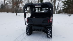
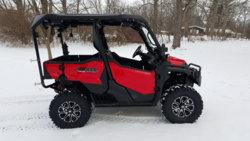
Here is a rear view you can click on the pictures and zoom in. Though you can't tell from this angle the front side of the rear A arm guards angle up quite a bit for additional protection of the A arms.1f2cf36551104b335779d1dda4038beb
 
joeymt33

joeymt33

i4WD=imitated 4WD
Moderator
Lifetime Member
Supporting Member
Club Contributor
Mar 17, 2015
11,096
39,129
113
Guntersville, AL
Ownership

  1. 1000-3

  2. 1000-5
Thank you @JACKAL
 
ghost

ghost

Well-Known Member
Lifetime Member
Dec 4, 2015
993
1,874
93
BC
Had a blast today on maiden voyage. P1K5D performed beyond my expectations. Nasty weather but still logged 40 miles even with a 2 yr old.

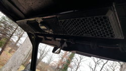
How do you like the hard panel?
I'm thinking the same thing to reduce dust in cab - actually it's tiny mud droplets but they settle everywhere inside.
Does it still work ok for back seat passengers?
 
JACKAL

JACKAL

Ancient Honda fanboi
Moderator
Lifetime Member
Supporting Member
Club Contributor
Jun 11, 2015
40,212
275,470
113
Pioneer, TN
Ownership

  1. 1000-5

  2. Talon X4
How do you like the hard panel?
I'm thinking the same thing to reduce dust in cab - actually it's tiny mud droplets but they settle everywhere inside.
Does it still work ok for back seat passengers?
The rear hard panel worked just fine with the sliding glass window open you can talk to passengers in the back seats just fine. Can't comment on dust yet has been raining heavily each day since I picked it up on the afternoon of 12/22. But I expect it will be just fine. I like it alot better than the soft rear panel on my P500.
 
JACKAL

JACKAL

Ancient Honda fanboi
Moderator
Lifetime Member
Supporting Member
Club Contributor
Jun 11, 2015
40,212
275,470
113
Pioneer, TN
Ownership

  1. 1000-5

  2. Talon X4
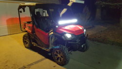
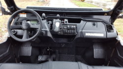
Getting ready to head home to the shop, I am off work until 1/3/16 and have many items waiting on me to install on the P1K5D in the upcoming week. Stay tuned as thing will progress very quickly starting 12/28/15. Will update with detailed pics, first things to do is dual battery install, Bussman relay & fused 10 port power distribution module, Winch and pod lights.
 
  • Like
Reactions: p500fan
advertisement
joeymt33

joeymt33

i4WD=imitated 4WD
Moderator
Lifetime Member
Supporting Member
Club Contributor
Mar 17, 2015
11,096
39,129
113
Guntersville, AL
Ownership

  1. 1000-3

  2. 1000-5
N

Ned

Active Member
May 12, 2015
241
183
43
West Kentucky
Ownership

  1. 1000-5
I am looking forward to see what location you choose for your Bussman relay. I have a similar setup and have been looking around how others have managed placement. Can I ask what is the size of the hole in the glass windshield for the windshield wiper? I don't see the wiper in your photos but I maybe I just don't see it. I assume you haven't place it yet as you are going with your own power distribution setup.
 
JACKAL

JACKAL

Ancient Honda fanboi
Moderator
Lifetime Member
Supporting Member
Club Contributor
Jun 11, 2015
40,212
275,470
113
Pioneer, TN
Ownership

  1. 1000-5

  2. Talon X4
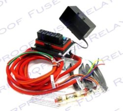
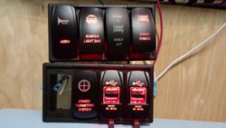
I am planning on having a total of twelve rockers divided into two gangs of six per row of which two will be a double port 3.2 amp USB power port with red backlighting giving me (4) total powered USB ports for charging phones, GoPro, GPS, etc. the remaining 10 switches will perform the various electrical functions all through a Cooper Bussman power distribution module, this module has an 6 gauge main Positive power line & 8 gauge Negative grounding line both to the secondary Oddessey 925 Battery, then there is (5) output wires with 15 amp fuses without relays for running the minor stuff like pod lights, horn, etc. There is (5) 35 amp relay lines with 30 amp fuses for each line / relay with a 14 gauge wire to go to the switched power to close the relay and (5) 10 gauge wires coming out of the fused relay to power bigger accessories, Light bars, Stereo, etc.

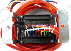
Here is the power distribution module as received, all prewired and includes all necessary items like heat shrink and butt connectors, etc. Bussman PDM Kit
Here is a detail of the top with cover off and underneath detail:
Bussman Top cover off
Bussman Bottom

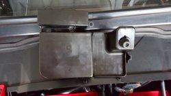
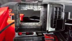
Looking under the hood for a place to mount this PDM there was not a location I liked with the metal standoff attached to the Bussman PDM so I removed the standoff then you have the prewired bundle coming from underneath so that negates a flush mount. Then the light went off that the large black cover that covers the air pre-cleaner and intake tube could house this PDM in a recessed cutout in a very tidy fashion.

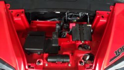
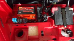
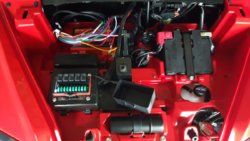
OEM under the hood untouched, then black air intake cover removed:
20151228 131831 20151228 132332

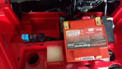
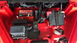
Dropping in the 2nd battery, note the added L connectors on terminals:
20151228 132325 20151228 132416

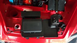
Intended location for PDM once cover is on & PDM setting in place of hole to be cut out:
20151228 132850 20151228 132931
Roughed cutout in black cover for PDM insertion from underneath & 3/4" hole on side for all wiring to exit.
20151228 134858 20151228 140305

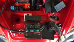
PDM screwed in place with wires pulled through & lid secured in place. All neat and tidy without using up any additional space under the hood.
20151228 141847 20151228 142018

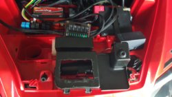
I will seal around the PDM mounting holes with black RTV silicone and as shown you do not lose any space where you can mount anything else needed. The only other spot big enough (that suited me) with the PDM standoff attached is where I want to mount the Battery Isolator which I will not have until 12/30/15. As viewing the bottom right picture with the cap on the PDM it does interfere with the hood slightly and needs to come down 3/8 of an inch on the left side where the hood lies with the body. Thankfully there is 1" of clearance underneath the PDM cover so a little work with the heat gun will reshape this so it doesn't touch the hood when secured down.

Well time to start making a couple dozen Jumper wires for all my lighted switches, no rest for the wicked. :p
 
N

Ned

Active Member
May 12, 2015
241
183
43
West Kentucky
Ownership

  1. 1000-5
I am planning on having a total of twelve rockers divided into two gangs of six per row of which two will be a double port 3.2 amp USB power port with red backlighting giving me (4) total powered USB ports for charging phones, GoPro, GPS, etc. the remaining 10 switches will perform the various electrical functions all through a Cooper Bussman power distribution module, this module has an 6 gauge main Positive power line & 8 gauge Negative grounding line both to the secondary Oddessey 925 Battery, then there is (5) output wires with 15 amp fuses without relays for running the minor stuff like pod lights, horn, etc. There is (5) 35 amp relay lines with 30 amp fuses for each line / relay with a 14 gauge wire to go to the switched power to close the relay and (5) 10 gauge wires coming out of the fused relay to power bigger accessories, Light bars, Stereo, etc.

Here is the power distribution module as received, all prewired and includes all necessary items like heat shrink and butt connectors, etc. View attachment 8435
Here is a detail of the top with cover off and underneath detail:
View attachment 8436 View attachment 8437

Looking under the hood for a place to mount this PDM there was not a location I liked with the metal standoff attached to the Bussman PDM so I removed the standoff then you have the prewired bundle coming from underneath so that negates a flush mount. Then the light went off that the large black cover that covers the air pre-cleaner and intake tube could house this PDM in a recessed cutout in a very tidy fashion.

OEM under the hood untouched, then black air intake cover removed:
View attachment 8438 View attachment 8441

Dropping in the 2nd battery, note the added L connectors on terminals:
View attachment 8439 View attachment 8440

Intended location for PDM once cover is on & PDM setting in place of hole to be cut out:
View attachment 8442 View attachment 8443
Roughed cutout in black cover for PDM insertion from underneath & 3/4" hole on side for all wiring to exit.
View attachment 8444 View attachment 8445

PDM screwed in place with wires pulled through & lid secured in place. All neat and tidy without using up any additional space under the hood.
View attachment 8446 View attachment 8447

I will seal around the PDM mounting holes with black RTV silicone and as shown you do not lose any space where you can mount anything else needed. The only other spot big enough (that suited me) with the PDM standoff attached is where I want to mount the Battery Isolator which I will not have until 12/30/15. As viewing the bottom right picture with the cap on the PDM it does interfere with the hood slightly and needs to come down 3/8 of an inch on the left side where the hood lies with the body. Thankfully there is 1" of clearance underneath the PDM cover so a little work with the heat gun will reshape this so it doesn't touch the hood when secured down.

Well time to start making a couple dozen Jumper wires for all my lighted switches, no rest for the wicked. :p

Thanks so much for the detail Jackal. I think your approach is very bold and creative, I would not have thought of going that route. On one hand, I hate to be wuss here waiting to see how other thinking men solve these issues, but on the other, why not gain by their experiences.
I also want to thank you for the info on the hole size in the glass windshield. I see that there is a, on the cheap, hand manipulated wiper that may fit that hole and it gives me additional options if I buy the glass windshield, at least until I either spring for the Honda model or wait until an after market becomes available.

On the Bussman relay...isn't there 6 fused and 6 relayed circuits? I am thinking of powering all 6 of my lighted switches (which will control the relay circuits) with one or more of the fused circuits. When I first got this PDM I thought it may have been designed so that each fused circuit would power the switches for the relay circuits, but after much tested inquiry on this board, I now understand that low amp power can be jumped switch to switch like the ground, leaving a number of fused circuits for additional low amp devices. I don't know how much power it takes going to a switch to trigger the relay, so I don't really know how many switches I can power with say a 15 amp fused circuit? Lastly, you answered one questions that I have not asked which was where do you all get your jumpers. You make your own. Thanks again.
 
JACKAL

JACKAL

Ancient Honda fanboi
Moderator
Lifetime Member
Supporting Member
Club Contributor
Jun 11, 2015
40,212
275,470
113
Pioneer, TN
Ownership

  1. 1000-5

  2. Talon X4
On the Bussman relay...isn't there 6 fused and 6 relayed circuits?
I don't know how much power it takes going to a switch to trigger the relay, so I don't really know how many switches I can power with say a 15 amp fused circuit? Lastly, you answered one questions that I have not asked which was where do you all get your jumpers. You make your own. Thanks again.

There are 10 Circuits total all 10 are fused five with 15 amp non relay and five with 30 amp with 35 amp relays.
I do not know how much power draw it takes to "trigger" the relay either but I have seen plenty of pictures where 5-8 switched are all being powered by one 14 gauge wire to "trigger" a relay corresponding to those switches. That being the case I will power all 5 relayed switched from one keyed powered source (Honda black/white wire 15 amp fused by Honda). Yes you make all your jumpers will have pictures of them later today all plugged into a bank or two of switches.
 
N

Ned

Active Member
May 12, 2015
241
183
43
West Kentucky
Ownership

  1. 1000-5
There are 10 Circuits total all 10 are fused five with 15 amp non relay and five with 30 amp with 35 amp relays.
I do not know how much power draw it takes to "trigger" the relay either but I have seen plenty of pictures where 5-8 switched are all being powered by one 14 gauge wire to "trigger" a relay corresponding to those switches. That being the case I will power all 5 relayed switched from one keyed powered source (Honda black/white wire 15 amp fused by Honda). Yes you make all your jumpers will have pictures of them later today all plugged into a bank or two of switches.

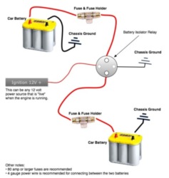
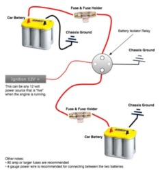
I have the part, don't know where I saw six, 5 is absolutely correct, and after writing this I was reading other posts, I see that all switches can be powered with a single hot jumped so that answers that. So to be sure my head is on straight, while running a second battery with an isolator like this one shown, my idea was to tap the black/white to what is labeled "ignition source" here? Or do I have the whole concept wrong?200 amp battery isolator relay diagram
 
JACKAL

JACKAL

Ancient Honda fanboi
Moderator
Lifetime Member
Supporting Member
Club Contributor
Jun 11, 2015
40,212
275,470
113
Pioneer, TN
Ownership

  1. 1000-5

  2. Talon X4
I have the part, don't know where I saw six, 5 is absolutely correct, and after writing this I was reading other posts, I see that all switches can be powered with a single hot jumped so that answers that. So to be sure my head is on straight, while running a second battery with an isolator like this one shown, my idea was to tap the black/white to what is labeled "ignition source" here? Or do I have the whole concept wrong?200 amp battery isolator relay diagram


To feed the relay and led lights inside the switches only you tap in here as shown: P1000 - Honda Pioneer 1000 - Key On Power. | The Honda Side by Side Club!

All the main power comes from the heavy gauge wire the PDM connects to the 2nd battery with. I will have it all step by step in pictures tomorrow. Only waiting on the isolator and cables to connect the two batteries.
 
N

Ned

Active Member
May 12, 2015
241
183
43
West Kentucky
Ownership

  1. 1000-5
JACKAL

JACKAL

Ancient Honda fanboi
Moderator
Lifetime Member
Supporting Member
Club Contributor
Jun 11, 2015
40,212
275,470
113
Pioneer, TN
Ownership

  1. 1000-5

  2. Talon X4
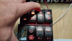
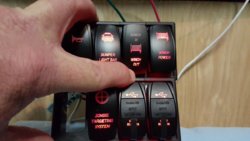
I ended up getting about 1/2 my switches today, enough to play with in setting up the jumper lines for the whole set. What I have pictured below is incomplete (using two 4 switch banks instead of two 6 switch banks*) but serves the purpose for now in demonstrating on setting up the various switches. *Note to self when ordering from Amazon make sure it coming from USA not China or you wait 6 weeks, live n learn ;)

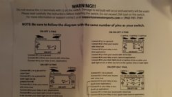
Switch Schematic for SVT switches:
20151229 154454


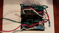
So for the wiring pictured below here is the layout:
RED - Hot wire coming from Honda Black/White ignition keyed accessory wire to the switches power in terminal.
WHITE - Hot wire coming from Honda Brown light switch wire to switched backlit LED's - Switches light up when headlights on.
GREEN - Ground wire from switches to ground.
BLACK - jumper wire from Winch Power ON/OFF to Winch Momentary IN/OUT rocker - A secondary measure of killing power to winch solenoid.
20151229 154424

Initial testing, everything lights up perfect:
20151229 153514 20151229 153324 20151229 153331

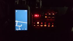
Well that's it for today, tomorrow will be installing the dual battery wiring kit with isolator, cutting out a temp switch plate from OEM skid plate material, mounting the switches in the switch plate & dash, installing (4)- 18 watt pod lights for front & rear added lighting, and maybe even getting around to getting the GPS installed.
 
tjoreo

tjoreo

Well-Known Member
Lifetime Member
Feb 18, 2015
1,028
1,981
113
Southern Idaho
Ownership

  1. 1000-5
Like the setup. I told you I would be watching you like Santa and it looks like you have been a very busy boy. I went ahead and ordered the PDM and was curious what items you were going to put on the lower 15 amp non-relayed fuses? Something I never thought about when I ordered it but it says in the directions that these items are hot at all times, so I was just curious what you were going to use them for. I'll keep watching.
 
  • Like
Reactions: JACKAL
advertisement

About us

  • Our community has been around for many years and pride ourselves on offering unbiased, critical discussion among people of all different backgrounds. We are working every day to make sure our community is one of the best.

User Menu

Buy us a beer!

  • Lots of time and money has gone into making sure the community is running the best software, best designs, and all the other bells and whistles. Care to buy us a beer? We'd really appreciate it!

    Beer Fund!

    Club Membership!