

T
You are using an out of date browser. It may not display this or other websites correctly.
You should upgrade or use an alternative browser.
You should upgrade or use an alternative browser.

Hondasxs
Club Founder
Staff member
Lifetime Member
Supporting Member
This switch has a nice wire diagram in the images.
 store.hondasxs.com
Sent from my SM-G996U using Tapatalk
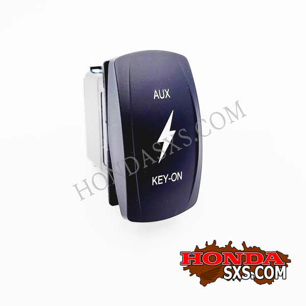
AUX & Key-on Rocker Switch, DPDT, ON/OFF/ON.
DPDT ON/OFF/ON switch. OTR Carling V-Series This is a maintained ON/OFF/ON switch, not momentary. Two independently wired LEDs Rated 20A 12V No rear barriers between terminals. Insulated 1/4" female quick disconnect terminals can be used. This is a 10 terminal switch. O-Rings installed on the...
store.hondasxs.com
Sent from my SM-G996U using Tapatalk
Remington
POIDH Enforcement Officer
Lifetime Member
Supporting Member
Welcome from Michigan!I followed this diagram from the site ..
I'm at the DPDT Switch ..Not sure what switch I need 7 pin ..10 pin ??? and which numbered pin do the wires connect to? Diagram linked
Got some Pics and info about your rig? Kinda a big deal here when you join. Pics Or It Didnt Happen! as we like to say. Also Pics and a explanation of what your trying to do will help us to answer your question. Otherwise its like Throwing darts at a blank board.
The club store sells a good master switch and the diagram shown is how I wired mine. Before that I used a 7 pin wired like thisI followed this diagram from the site ..
I'm at the DPDT Switch ..Not sure what switch I need 7 pin ..10 pin ??? and which numbered pin do the wires connect to? Diagram linked

T
Thanks! Brand new (middle of 2022) 2021 1000-5 LE. I'm doing the dual battery install ... using the dual battery wiring diagram (with key-on and bypass) from the site. I'm using the accessory bus .. I'm confused about the DPDT Switch .. 7 pin 10 pin? What number on the switch do the wires go to?I've seen a bunch of diagrams but none with this bus. And the the bus is dark red?Welcome from Michigan!
Got some Pics and info about your rig? Kinda a big deal here when you join. Pics Or It Didnt Happen! as we like to say. Also Pics and a explanation of what your trying to do will help us to answer your question. Otherwise its like Throwing darts at a blank board.
More pics to come.


Hondasxs
Club Founder
Staff member
Lifetime Member
Supporting Member
I'm still a little confused as to what you are asking.
Can you clarify "key on bypass". What do you mean?
----- The key-on harness from the club store?
As for what the DPDT switch will look like depends on which one you buy and its layout.
See the link to the HondaSxS 10p one I posted above and look at the wiring diagram.
Regarding the added bus.
It looks to be constant, so you could collect constant power there if you wanted to.
Also, Is that a negative bus I see?
Does it ground to the second battery and ONLY to the second battery?
You need to ensure proper power loops back to the second battery.
Grounding to the primary or to the frame could alter this path.
T
I'm still a little confused as to what you are asking.
Can you clarify "key on bypass". What do you mean?
----- The key-on harness from the club store?
As for what the DPDT switch will look like depends on which one you buy and its layout.
See the link to the HondaSxS 10p one I posted above and look at the wiring diagram.
Regarding the added bus.
It looks to be constant, so you could collect constant power there if you wanted to.
Also, Is that a negative bus I see?
Does it ground to the second battery and ONLY to the second battery?
You need to ensure proper power loops back to the second battery.
Grounding to the primary or to the frame could alter this path.
I'm doing the rocker switch with the two options ..key-on in one position and bypass in the other poison with no key needed.I'm still a little confused as to what you are asking.
Can you clarify "key on bypass". What do you mean?
----- The key-on harness from the club store?
As for what the DPDT switch will look like depends on which one you buy and its layout.
See the link to the HondaSxS 10p one I posted above and look at the wiring diagram.
Regarding the added bus.
It looks to be constant, so you could collect constant power there if you wanted to.
Also, Is that a negative bus I see?
Does it ground to the second battery and ONLY to the second battery?
You need to ensure proper power loops back to the second battery.
Grounding to the primary or to the frame could alter this path.
right now I have a 7 pin switch .. I saw the 10 pin and the diagram that goes with it..
Good catch on the negative bus... I ordered the wrong color and have a red one coming.
The diagram shows the key on coming into the switch (top left) and the dual battery coming into switch (bottom Left) ... and then coming out the other side
Good catch on the negative bus .. I was sent the wrong color.. red on on the way.I'm still a little confused as to what you are asking.
Can you clarify "key on bypass". What do you mean?
----- The key-on harness from the club store?
As for what the DPDT switch will look like depends on which one you buy and its layout.
See the link to the HondaSxS 10p one I posted above and look at the wiring diagram.
Regarding the added bus.
It looks to be constant, so you could collect constant power there if you wanted to.
Also, Is that a negative bus I see?
Does it ground to the second battery and ONLY to the second battery?
You need to ensure proper power loops back to the second battery.
Grounding to the primary or to the frame could alter this path.
I saw the 10 pin with diagram ..right now I only have a 7 pin.
The rocker switch two options are what I'm trying to do ..key-on in one position and key off in the other to run my accessories.
I've never done a seven pin before and wanted to make sure the wires were going to the right pins on switch.
Thanks for all the help.
Hondasxs
Club Founder
Staff member
Lifetime Member
Supporting Member
Ok.
Here is your 7 pin layout.
- pin 4 is key-on.
- pin 5 is to the stinger.
- pin 6 will be constant (2a fused battery power)
Question?
How do you want the switch LED's to work?
I perfere ON when turned on. Off when off.
To do this. Jump pin #5 to pin #2.
Also ground pin #7
If your switch works reverse. Key-on= key-off. Then just flip pin # 4 and 6.
Hope that helps.
Sent from my SM-G996U using Tapatalk
Hondasxs
Club Founder
Staff member
Lifetime Member
Supporting Member

T
Awesome!...ThanksOk.
Here is your 7 pin layout.
- pin 4 is key-on.
- pin 5 is to the stinger.
- pin 6 will be constant (2a fused battery power)
Question?
How do you want the switch LED's to work?
I perfere ON when turned on. Off when off.
To do this. Jump pin #5 to pin #2.
Also ground pin #7
If your switch works reverse. Key-on= key-off. Then just flip pin # 4 and 6.
Hope that helps.
Sent from my SM-G996U using Tapatalk
advertisement
Hondasxs
Club Founder
Staff member
Lifetime Member
Supporting Member
T
Almost ..The switch is working but I'm still looking into one small issue ...I'll explain later. I'm also working on getting dual volt meters to work with the relay that came with the True isolator. Just not enough time.Any update?
You get this done?
Thanks .. I'll post soon
T
Almost ..The switch is working but I'm still looking into one small issue ...I'll explain later. I'm also working on getting dual volt meters to work with the relay that came with the True isolator. Just not enough time.
Thanks .. I'll post soon
Almost ..The switch is working but I'm still looking into one small issue ...I'll explain later. I'm also working on getting dual volt meters to work with the relay that came with the True isolator. Just not enough time.
Thanks .. I'll post soon
2nd pic is the wiring I went with ...center pin hot (left) with out on the bottom pin... right side center pin hot with out on the top pin as in pic.Almost ..The switch is working but I'm still looking into one small issue ...I'll explain later. I'm also working on getting dual volt meters to work with the relay that came with the True isolator. Just not enough time.
Thanks .. I'll post soon
Auxbeam 8 gang switch panel
Crossroads dash panel for Limited Edition
Big thanks to everyone that helped.


Similar threads
C
- Replies
- 7
- Views
- 847
- Replies
- 43
- Views
- 3K
C
- Replies
- 19
- Views
- 591